
This is an old revision of the document!
Part I) Getting the angles and calculating the velocities from the encoders:
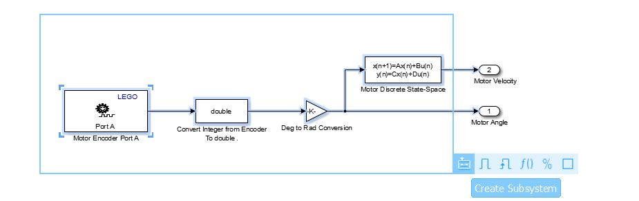
- Motor Encoder Logic: We can get the angle from the encoder using the “Encoder” block, the encoder block returns an integer value in degrees.However for our calculations is better to use a variable with better precision, so we use a “Data Type Conversion” block to convert the angle from integer to double precision. After , we need to convert this angle in degrees to radians , so a “Gain” block is used for this task. Using a “Discrete State – Space” block we can derive the velocity , using the angle as input.
1) Drag the following blocks to the work area: 1x Encoder / 1x Data Type Conversion / 1x Gain / 1x Discrete State Space / 2x Output (Out1).
2) Double click on the following blocks to modify its parameters:
- Encoder : Change the port to port A, reset mode as no reset, and sample time to -1.
- Data Type Conversion : Output type to double , Integer rounding mode to Simplest.
- Gain: change the value to pi/180 with element wise multiplication.
- Discrete State Space: Change the A,B,C,D matrix to the name of your A,B,C,D matrix that represents your discrete state space model stored on the workspace. Use the Sample time as you want ,can be 0.010. ( Be sure to use the same Sample time on the pendulum encoder and on the model configuration – will be explained later)
- Output: Change the name for Motor Angle and Motor Velocity.
3)Connections: Connect the blocks as shown in the picture. After connecting, select all the blocks and create a subsystem.
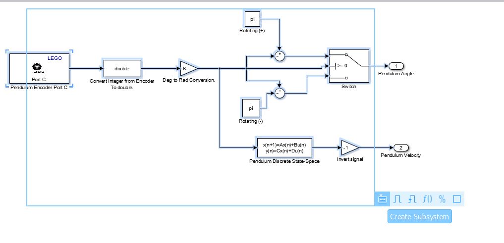
- Pendulum Encoder Logic:Follows the same logic of the motor encoder. However, we will introduce a switch block to act as a conditional clause to change the Pendulum position value (to be 0 on the Top, because as default, the 0 position will be the position when the system initialize).We have three inputs on the Switch Block, the top and the bottom inputs are what we want from the conditional expression and the middle input will act as our conditional clause. I chose to the 0 angle to be on the top equilibrium position, any position to the left of this vertical line to be positive angles, and any position to the right of this vertical line to be negative. On this case, the conditional clause will be when the pendulum angle is greater or equal to 0, it will receive the -angle +pi (this way, it will start from 180, all the way to 0) and if this is not true, it will receive –angle –pi (this way it will start from -180 all the way to 0 at the top). Note that because the angle is decreasing from 180 at the bottom to 0 at the top, the velocity when the pendulum is falling will be with an inverted signal (we use a -1 gain to the output velocity and this problem is solved). The Switch works this way: if the conditional clause is true , will pass by the top input , if is false , it will pass by the bottom input.
1) Drag the following blocks to the work area:1x Encoder / 1x Data Type Conversion / 1x Gain / 2x Constant /2x Sum/ 1x Switch / 1x Discrete State Space / 2x Output (Out1).
2)Double click on the following blocks to modify its parameters:
- Encoder:Change the port to port C, reset mode as no reset, and sample time to -1.
- Data Type Conversion: Output type to double, Integer rounding mode to Simplest.
- Gain:Change one block to pi/180 and one to -1 (both with element wise multiplication).
- Discrete State Space:Change the A,B,C,D matrix to the name of your A,B,C,D matrix that represents your discrete state space model stored on the workspace. Use the Sample time as you want ,can be 0.010. ( Be sure to use the same Sample time on the pendulum encoder and on the model configuration – will be explained later)
- Output:Change the name for Pendulum Angle and Pendulum Velocity.
- Constants: Change the value to pi (pi should be stored on your Matlab workspace).
- Switch: Change the criteria to u2 >= Threshold and Threshold to 0.
- SUM:Change one to ( +-|) to be used on the top input , and one to (–|) to be used on the bottom input.
3) Connections:Connect the blocks as shown in the picture. After connecting, select all the blocks and create a subsystem.
End of Part I): For better understanding ,organize your subsystem as shown in the picture.Pay attention to the output order (OUTPUT NUMBER) , you should follow the same order as shown in the picture (to create the right [u] matrix).

Part II) Calculating the input to be sent to the motor
- Input Calculation Logic:Now that we have our “[x]” matrix with the states of our system , we can calculate the motor input as [K]*[u] , where [K] is our optimal gain matrix from LQR (Can be calculated using Matlab). We just need to do a matrix multiplication and its done.