Table of Contents
How To Control an Unipolar Stepper Motor with LEGO NXT Using ULN2003A
Author: Xinke (Rebecca) Cao
Email: caox1@unlv.nevada.edu
Date: Last modified on 08/04/2017
Keywords: unipolar stepper motor, LEGO NXT, transistors, IRF510
Motivation and Audience
In many instances in engineering, precise rotary movement is necessary to produce accurate results. The stepper motor, a motor that rotates a certain amount of degree per step; therefore, allow the user to track the total amount rotated. In addition, the rotation speed can be controlled through programming.
The stepper motors resembles the dynamixels used in Darwin-OP; therefore, learning to operate the stepper motors allows more possibilities on the types of mechanisms can be built that can be controlled by the LEGO NXT Brick. Furthermore, the ability to track the amount of rotation that the stepper motor has made allow for more accurate determination of the state (position, velocity, acceleration) of any mechanism that is attached to the stepper motor.
Parts List and Sources
- (1) 9V battery
- (1) 9V battery snaps
- (1) 28BYJ-48 5V unipolar stepper motor
- (1) ULN2003A
- (4) 3.3k Ohms resistors
- (1) PCF8574A
- (1) NXT to breadboard adaptor
- (1) NXT Brick
- (various quantities) gauge wires
Here is the demo of the motor turning with the following schematics and coding.
All the codes can be found here, titled “Stepper_ULN2003A_Basic.nxc”.
Circuit Schematics
The circuit is based on the extreme NXT site. Below is a picture of the circuit schematics.
 D0 controls blue.
D1 controls pink.
D2 controls yellow.
D3 controls orange.
The integrated circuit that is connected to the PCF8574A is the ULN2003A. The ULN2003A is an array of seven Darlington transistors that amplifies current from the PCF8574A and outputs the voltage supplied to its common port to drive the stepper motor. This is similar to how the IRF510 amplifies the current and acts as a switch to allow specific wires on the stepper motor to obtain enough voltage and current. However, when you input a LOW signal to the ULN2003A, it will output a HIGH signal. Therefore, in the code, we need to adjust the bit values output by the PCF8574A to account for this change.
Construction
Step 1
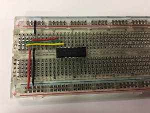
Insert a PCF8574A.

Insert the clock line from PCF8574A to the NXT adaptor.

Insert the data line.

Insert the voltage source to the PCF8574A.

Insert the ground lines to the NXT Brick.

Ground the pins on PCF8574A.

Step 2
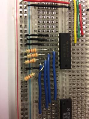
Insert a ULN2003A.

Add the ground to the ULN2003A and the 9V source to the ULN2003A.


Add the data lines from the PCF8574A to the ULN2003A's input ports.

Add resistors to the digital output pins of PCF8574A that are in use to provide enough currents.


Step 3
Insert the NXT adaptor.


Step 4
Insert the stepper motor to the output pins of the ULN2003A.

Connect the red wire from the stepper motor to a 9V voltage source.


Step 6
Connect the battery.

Programming
First, I defined where the input port and the address for the PCF8574 will be.
#define I2Cport S1 // Port number
#define I2CAddr8574 0x70 // I2C address
Then, in the main task, the variables for the function I2CBytes() will be initialized.
byte WriteBuf[2];
byte ReadBuf[];
int RdCnt = 1;
Next, since the PCF8574A is connected to the NXT on input port S1; therefore, PCF8574A will be initialized and set up for writing to the PCF8574.
SetSensorLowspeed (I2Cport); // PCF8574A connect to NXT on S1
WriteBuf[1] = 0x00; // i.e. write zeros to port sets up PCF8574A for writing
WriteBuf[0] = I2CAddr8574; // i.e. address is 0x70
I2CBytes(S1, WriteBuf, RdCnt, ReadBuf);
To allow the motor to turn, a sequence of data has to be send to the motor in order for the motor to turn in a certain direction. In this case, the motor will be turning in clockwise direction.
The sequence that the PCF8574A will be sending to allow the transistors to open or close is as follows:
  WriteBuf[1] = 12;  //1100
  I2CBytes(S1, WriteBuf, RdCnt, ReadBuf);
  Wait(10);
  WriteBuf[1] = 9;  //1001
  I2CBytes(S1, WriteBuf, RdCnt, ReadBuf);
  Wait(10);
  WriteBuf[1] = 3;   //0011
  I2CBytes(S1, WriteBuf, RdCnt, ReadBuf);
  Wait(10);
  WriteBuf[1] = 6;   //0110
  I2CBytes(S1, WriteBuf, RdCnt, ReadBuf);
  Wait(10);
To reverse the direction that the stepper motor is turning, the sequence can be reversed.
Final Words
The purpose of this tutorial is to allow the users of the NXT Brick learn how to control a stepper motor through an NXT interface.
Building from this tutorial, one can control the speed of the stepper motor and the direction of the stepper motor by altering the wait time between each signal and the sequence of the signal.
If you have any questions, please email me at caox1@unlv.nevada.edu.
