Table of Contents
ARToolkit
Author: Dylan Wallace Email: wallad3@unlv.nevada.edu
Date: Last modified on 08/28/16
Keywords: ARToolkit, Computer Vision, Software, SDK, Path Planning

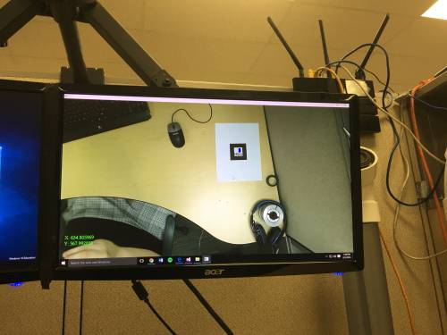
The photo above depicts coordinate tracking of a marker with the ARToolkit SDK, which allows you to track the relative position of something with a marker attached to it. The big picture problem is tracking movement for computer vision and navigation applications. Solving this partially or completely is important because it allows for objects to be quickly located, and used in programs for various applications. This tutorial shows you how to install, setup, and use the ARToolkit, and takes approximately 3 hours to complete.
Motivation and Audience
This tutorial's motivation is to provide an introduction to the ARToolkit and its applications. Readers of this tutorial assumes the reader has the following background and interests:
* Know how to use basic Linux and Windows commands
* Perhaps also know how to program in C/Cpp, especially with Visual Studio.
* Perhaps additional background needed may include experience with other frameworks such as OpenCV or OpenGL.
* This tutorial may also attract readers who are interested in path planning, computer vision, NXT applications, or augmented reality.
Note: The ARToolkit has difficulty recognizing many cameras on Linux. I recommend using Windows 8.1 or higher for these tutorials. Any high-resolution camera should give you good results from this tutorial, but here is the camera that I used when working with the ARToolkit.
The rest of this tutorial is presented as follows:
- Final Words
Installation and Setup
Step 1: Download
Start by downloading the ARToolkit SDK, specific to your operating system.
Step 2: Install
Once you have downloaded the necessary package for your operating system, install the ARToolkit SDK using these instructions specific to your operating system.
Step 3: Obtain Missing DLLs
If you are running on a newer Windows installation, it is possible that you do not have the Visual Cpp Redistributables required to run the ARToolkit SDK. I recommend downloading them here before trying to run any ARToolkit examples.
Using the ARToolkit
Step 1: Printing markers/fiducials
The most important part of running any examples or other programs for ARToolkit is making sure your markers or fiducials are printed properly. For the simple examples from ARToolkit, we will use the Hiro pattern, found in C:\Program Files (x86)\ARToolKit5\doc\patterns. Optionally, here is a download of the file needed to print the marker. When printing this marker, make sure that your printer is printing at the highest settings, with contrast as high as possible for the image recognition.
Step 2: Running the Example
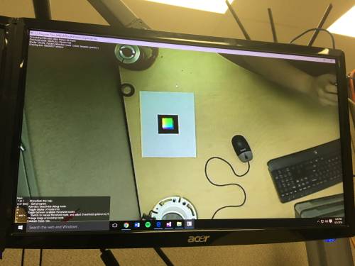
Once you have printed your marker, you are now able to run the most basic example that ARToolkit provides for testing the SDK. Go into your ARToolkit5 folder, and run the simpleLite program located in the bin folder. Accept the default values that popup for the video configuration, and the program will begin to run. Make sure that your camera has a clear view of your area, and that the marker is not obstructed by other objects. If your ARToolkit SDK is working properly, then your output should look something like this:
When you move the marker along your surface, or even into the air, the colored cube should follow the marker. If not, then you may need to calibrate your camera parameters.
Optional: Step 3: Calibrate Camera
If the marker is not recognized by the ARToolkit simpleLite program, or if the marker tracking is not smooth, you may want to calibrate your camera parameters. Before calibrating your camera, you will need to print out the calibration chessboard. This should be located with the other ARToolkit patterns (in the doc folder of the ARToolkit5 directory), but i have also linked it here for download. Glue this page to a flat surface such a foam-board or cardboard so that the squares do not move around during calibration.
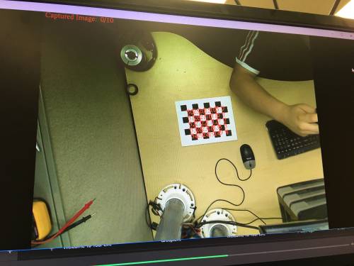
Open the bin folder inside the ARToolkit5 directory, and run the calib_camera.exe file as administrator. Select the defaults for the camera configuration before the program runs. Once your video is streaming, use the chessboard pattern glued onto a flat surface, to calibrate the camera. The video will look for all the corners on the chessboard, and these will turn red when it is ready to use these for calibration. The output should look something like this when the chessboard is in full view:
Press space bar to capture the frame once all the corners have turned red. Keep your camera in a fixed position, and move the board with the pattern around your area. Try multiple angles and locations of the board, in order to get a variety of test data. Once you have captured 10 frames, the program will ask you to save the camera_para.dat file. Just press enter and the file will be saved into the bin folder. The last thing that you need to do is to replace this camera_para.dat file with the camera_para.dat file located in the Data folder of the bin directory.
Now run the simpleLite program again to see if these new parameters will help with tracking issues. If you are still having issues with tracking or recognizing markers, refer to the next step for debugging these issues.
Optional: Step 4: Debugging Marker Recognition
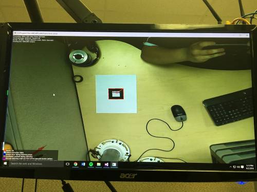
If even after calibrating your camera, you are still having marker recognition or tracking problems, then you may need to run the check_id.exe program provided in the ARToolkit5 directory, bin folder. This program will run through the different steps of the ARToolkit marker recognition process, and will help you figure out where your program is failing. You can use any of the square markers for this, but i recommend using the Hiro marker because it has the best contrast. When you start this program, your output should look something like this:
The marker will be outlined in a different color depending on the results of each step of the recognition process. Below I will explain the different cases you can have, and what to do to fix them.
Red Outline: This is the ideal scenario. This means that the program is able to detect the marker and full track its movement.
Light Blue Outline: This means that the pattern extraction has failed. This can be caused by uneven lines in printing, or scaling issues with the pattern onto the paper. Try fixing this by playing with the settings on your printer, or changing the layout/scaling of the marker on the page.
Blue Outline: This is a generic matching error. Often when this comes up, it can be similar problems to the light blue outline. When this code comes up, try printing a new marker, or recalibrating your camera.
Brown Outline: This is the most common error to get with the pattern recognition. This means that the contrast between the black and the white in the marker is not high enough, and therefore the marker is not properly processed. This can be fixed by adjusting printer settings, print quality settings on your computer, or by replacing ink/toner cartridges.
Purple/Pink Outline: These two outlines have to do specifically with the barcode recognition in the ARToolkit SDK. This can happen when barcodes are not printed properly, are skewed/scaled improperly on the page, or when something is obstructing the full barcode. Try clearing you image area, and try reprinting your barcodes to fix these errors. Also, make sure the barcode you are using is of an acceptable format for the ARToolkit SDK.
Green Outline: This means that the cutoff value for confidence matching was not reached by the program. Basically this means that the computer can vaguely recognize the marker as a marker, but its not completely sure if it actually is so it doesn't register it as one. In order to fix this make sure that your print is scaled correctly, that your marker is in full view, and that the print is of high quality (free of any streaks or fading).
Orange/Yellow Outline: This means that the maximum pose error was exceeded (yellow is for multi-marker). This means that the position error between the estimated image and the actual image is too great to get the transformation for the marker. This could most often be fixed by recalibrating your camera, improving lighting conditions, or getting a higher resolution camera.
Step 5: Creating a New Project
Once you have the example program simpleLite working well with marker recognition and tracking, you can move onto creating your own project. For developing your own projects using the ARToolkit, I recommend using Visual Studio 2013 or higher. Visual Studio has great support for the ARToolkit SDK, and all of their example projects have been provided as Visual Studio projects to modify or use as reference.
Note: With recent updates to ARToolkit, it can be very difficult to create a new project in Visual Studio for ARToolkit. If you run into these issues, I recommend doing your development within and already-existing project within the provided ARToolkit5 Solution. This will make the process much easier to debug, and take away the worries of creating and maintaining your own project.
To begin with creating a new project, simply open up Visual Studio and create an empty Visual Cpp project. Once you have created the empty project, you will need to add a .c file to the project. I named my file coordinate_tracking.c, because that was the use that I needed out of the ARToolkit. However, the ARToolkit is wide in its ability and uses.
Once you have created the project, you will need to add the include and library directories to your project. Do this by right-clicking the project, and going to Properties. Under properties, look for the VCpp Directories tab. First click on the drop-down for include directories, and in the pop-up window, add a new directory. The directory that you will need to add here is the include folder contained in the ARToolkit5 directory. Next, do the same thing for the library directories, except this time, add the lib folder of the ARToolkit5 directory. Now, go to the Input tab under the Linker tab, and select the additional dependencies drop-down. Here you will need to ARd.lib, ARvideod.lib, glut32.lib, and ARgsub_litd.lib.
Finally, you need to copy over some data from the ARToolkit5 bin folder. First, copy the Data folder over to your project folder. Next, copy DSVL.dll, DSVLd.dll, ARvideo.dll, and ARvideod.dll over into a new folder called Debug within your project folder.
Once you have all of this configured, you are ready to create your first program with the ARToolkit SDK.
Step 6: Modifying the Simple Program to Track Coordinates
Now that you have successfully setup, tested, and even created a new project with the ARToolkit SDK, you are finally ready to create custom code with the ARToolkit SDK. However, instead of creating all of the code from scratch, it is good to build off of the simpleTest.c program, provided with the ARToolkit SDK.
For reference on how the simpleTest.c program works wth the ARToolkit SDK, refer to this documentation provided by the University of Washington's Human Interface Technology Lab. Below I will describe the additions that I made to the simpleTest.c file in order to track real-world coordinates.
Adding Variables
Add these two variable declarations after line 31 of the simpleTest.c program. These lines will allow us to print the X and Y coordinates to the screen during processing.
32  char xValue[256];
33  char yValue[256];
It is also necessary to add some variables to the mainLoop function. Add these variable declarations after line 140. Keep in mind, xReal and yReal are dependent on what the camera displays in your view, and its real-world size.
141  double xCoord;
142  double yCoord;
143  double xReal = 38.5;
144  double yReal = 26.5;
Flipping Video
Since the camera setup is one that is looking down onto the table from a reversed angle, we need to flip the video both horizontally and vertically. We can achieve this by adding 15 lines of code in the main function, after line 54.
55  if (flipMode & AR_GL_FLIP_V)
56      flipMode = flipMode & AR_GL_FLIP_H;
57  else
58      flipMode = flipMode | AR_GL_FLIP_V;
59
60  argViewportSetFlipMode(vp, flipMode);
61
62  if (flipMode & AR_GL_FLIP_H)
63      flipMode = flipMode & AR_GL_FLIP_V;
64  else
65      flipMode = flipMode | AR_GL_FLIP_H;
66
67  argViewportSetFlipMode(vp, flipMode);
Removing Current Output
Befoire adding new output of the X and Y coordinates, we will want to remove the old output of the error valus and fps. To do this we just need to comment out lines 190, 194, and 195 for the fps.
189  if (count % 60 == 0) {
190      //sprintf(fps, "%f[fps]", 60.0 / arUtilTimer());
191     arUtilTimerReset();
192  }
193  count++;
194  //glColor3f(0.0f, 1.0f, 0.0f);
195  //argDrawStringsByIdealPos(fps, 10, ysize - 30);
For the error values, comment out lines 227, 229, and 230.
227  //sprintf(errValue, "err = %f", err);
228  glColor3f(0.0f, 1.0f, 0.0f);
229  //argDrawStringsByIdealPos(fps, 10, ysize - 30);
230  //argDrawStringsByIdealPos(errValue, 10, ysize - 60);
231  //ARLOG("err = %f\n", err);
Adding the X & Y Coordinates
Now we need to add the data for the X and Y coordinates to the screen. We can achieve this by adding 6 lines of code to the same area we just removed code from. Add these four lines after line 226.
227  xCoord = markerInfo[k].pos[0];
228  yCoord = markerInfo[k].pos[1];
229  sprintf(yValue, "Y: %f", (yReal / ysize)*yCoord);
230  sprintf(xValue, "X: %f", (xReal / xsize)*(xsize - xCoord));
Now add these two lines after line 232.
233  argDrawStringsByIdealPos(xValue, xsize - 10, 60);
234  argDrawStringsByIdealPos(yValue, xsize - 10, 30);
Changing the Graphics Models
Now that we are tracking the coordinates well, we just need to change to original 3D cube graphics into a small 3D marker. This can be achieved by simply editing two lines of code, 388 and 389.
388  glTranslatef(0.0f, 0.0f, 0.0f);
389  glutSolidCube(10.0);
Now the program should run smoothly and with accurate prediction of the real-world coordinates of the marker. Below is a video showing the coordinate tracking program in action.
Step 7: Tracking Multiple Markers
In order to use the ARToolkit SDK for tracking of objects or for any kind of computer vision application, you will often need to track more than one marker's position on the screen. One feature of the ARToolkit SDK that makes tracking multiple markers easier is their support for barcode-matrix markers. You can read more about these style of markers here. Essentially these barcode markers use a preset definition of matrix-style barcodes that correspond to individual IDs for a marker. This allows for individual markers to be pulled out specifically, but also for easier general tracking of all markers in loops. In order to use and track these barcode-style markers, we will need to add/change the code that we used for the original tracking.
Changing from pattern-detection to barcode-detection
First you will need to remove the references to the pattern style, because we are no longer using pattern-detection. To do this, comment out the lines in the beginning of the program around line 25 (depending on your code) where it defines the pattern name, and where it initializes the pattern handle.
//#define       PATT_NAME     "Data/hiro.patt"

//ARPattHandle     *arPattHandle;
Now you will need to add the barcode-detection to the main function. Places these two lines of code right before the function call for argMainLoop():
arSetPatternDetectionMode(arHandle, AR_MATRIX_CODE_DETECTION);
arSetMatrixCodeType(arHandle, AR_MATRIX_CODE_3x3_HAMMING63);
This will setup the marker-detection into barcode-matrix mode, allowing the ARToolkit to detect these markers instead of the traditional style of marker.
Tracking Coordinates of Multiple Markers
In order to consistently track the coordinates of multiple markers, you will need to alter the detection algorithm to associate one barcode ID with one instance of an array for storing your coordinates. To do this, add these lines of code to the main detection loop, after the IDs and CF values are logged to the ARConsole (Please change xCoord and yCoord to arrays that have the size as the amount of markers to track (currently 8 in this example)):
for (h = 0; h < 7; h++) {

  if (markerInfo[j].idMatrix == h) {
    yCoord[h] = (yReal / ysize)*(ysize - markerInfo[j].pos[1]);
    xCoord[h] = (xReal / xsize)*(markerInfo[j].pos[0]);
  }
}
Now we will be adding to this for loop in order to use our tracked coordinates for localization and navigation within an area.
Step 8: Using Multiple Markers for Localization and Navigation
In order to track the position of a robot or other vehicle using the ARToolkit, we will need to create an algorithm that creates relative coordinates for the robot based off of a known location of a stationary marker. This will allows us to create a kind of coordinate system that is independent of camera position or resolution. In order to do this, we will need to use one barcode marker (in most cases this will be number 0) fixed to a stationary location, and then reference this location in our code to get relative distances. This can be achieved by adding this block of code to the end of the for loop from the previous step (Please declare xCoordRel and yCoordRel as arrays, with the same size as xCoord and yCoord, at the beginning to the mainLoop() function):
if ((xCoord[0] != 0) && (yCoord[0] != 0) && (xCoord[h] < 1000) && (yCoord[h] < 1000) && (xCoord[h] > -1000) && (yCoord[h] > -1000)) {
  xCoordRel[h] = xCoord[h] - xCoord[0];
  yCoordRel[h] = yCoord[h] - yCoord[0];
  ARLOG("X(%d): %.1f; Y(%d): %.1f\n", h, xCoordRel[h], h, yCoordRel[h]);
  sprintf(xValue[h], "X(%d): %.1f", h, xCoordRel[h]);
  sprintf(yValue[h], "Y(%d): %.1f", h, yCoordRel[h]);
  argDrawStringsByIdealPos(xValue[h], 10, ysize - (25 * (h+1)));
  argDrawStringsByIdealPos(yValue[h], 130, ysize - (25 * (h+1)));
}
This if statement will store the positions of these markers into a separate array for relative positions, ensuring that normal tracking is unaffected by this. This will also output those relative distances to the screen using the last 5 lines of code. Since this is located within that same for loop from above, this will keep everything sorted into the proper positions of their array. The conditional statement for this step is checking to make sure that the reference marker is stored, and that the marker it is trying to calculate for is being recognized correctly (hence the over 1000 value). Once you have added this to your code, you should be able to efficiently and easily track multiple markers and their relative positions using the ARToolkit SDK. This has many potential applications for navigation and localization projects with robotics.
Final Words
This tutorial's objective was to teach how to setup, and use the ARToolkit SDK for tracking and navigation. Complete source code for the coordinate tracking program can be found here. Once the concepts were conveyed the reader could use the ARToolkit to write their own AR/object tracking programs in Visual C/Cpp.
Speculating future work derived from this tutorial, includes Potential Fields using the ARToolkit, and Potential Fields with Humanoid Robots such as Darwin. In the big picture, the problem of object tracking can be solved with this tutorial.
For questions, clarifications, etc, Email: wallad3@unlv.nevada.edu


