Table of Contents
Full Spectrum Laser Pro 36x24 Vector Cutting with SOLIDWORKS and Inkscape
Author: Santiago Ricoy
Email: [email protected]
Date: Last modified on 5/28/17
Keywords: laser cutter engraving etching burning cutting vector raster
The photo above depicts a completed laser cut of a leather wallet using the vector cut feature.
Motivation and Audience
This tutorial is targeted toward students new to the laser cutter and teaches them to design and cut parts using vector cuts on the laser cutter. This will cover a simple part to cut; for more complex projects it is recommended to ask to be put through the Laser 101 course. Please refer to the introductory post before cutting to verify no dangerous materials are cut.
Students reading this should have the following skill set:
* Familiarity with InkScape (or be comfortable with other vector graphics software)
* Have some introduction to SOLIDWORKS; this tutorial uses the 2016 version (or other 3D CAD software)
* Full understanding of material covered in the introductory tutorial: INTRO TUTORIAL
Primarily, the reader should understand how to: home, position, and focus the laser; as well as check the area covered by the current job.
The rest of this tutorial is presented as follows:
Items Required
To complete this tutorial, you'll need the following items:
- Computer running Windows 7 or higher
- RetinaEngrave3D installed with ethernet connection to laser
- Inkscape installed
- Material of choice to cut/engrave
- Nearby fire extinguisher (there are a few placed about the lab; know the nearest one)
Note: This tutorial requires using Inkscape to open a .DXF file. I ran into several issues where this would not work, between operating systems and Inkscape versions. To resolve these, I uninstalled any version of Python 3.XX+ and installed Python 2.XX. I installed Inkscape after doing this, and the issues I had were gone. Feel free to contact me if that solution doesn't work you (though I don't guarantee I can help).
WARNINGS
PLEASE READ THOROUGHLY
- NEVER leave the system unattended during operation
- Keep the area around the machine clutter free
- ALWAYS use air assist while cutting
- MONITOR all vector cuts, as rapid ignition occurs most often while vector cutting.
- CHECK AND CLEAN the laser system before use (i.e. remove honeycomb, check vent, wipe up dust/debris) as lasers pose a fire hazard in themselves; do not allow the danger to compound
- DO NOT OPERATE the machine with panels removed; it has a Class 4 laser system inside
- The laser produces INVISIBLE radiation; you will not know there will be a problem before there is one
Design Process
The steps here assume you have RetinaEngrave3D running and connected to the laser.
IMPORTANT NOTE: The laser doesn't cut ideally, so there is an amount of kerf depending on the material being cut. Kerf is the width of material burned away by the laser, which can make a cut either a bit too large, or a bit too small. This can be avoided by researching the material and thickness being used, and adjusting the design accordingly. For example, suppose we need a 50mmx30mm rectangle that must be cut from 5mm acrylic. A quick Google search for our expected kerf gives us a range, but it hovers around 0.2mm. We will be cutting around the outer edge of our rectangle so we would cut half of the kerf into the part. To counteract that, we move each line cut away by half the width of the expected kerf (0.1mm). Doing this on each side of our design will leave us with a 50.2mmx30.2mm rectangle, that when cut will yield a 50mmx30mm part.
Creating in SOLIDWORKS:
Begin a new sketch on whatever plane desired, and sketch out the shape of your part (working in millimeters is easiest between programs). I recommend following any of the usual conventions (fully define everything, check measurements, etc.).
The next steps can be done differently, and probably in a different order, but I feel this method is easiest to follow.
Once done with the sketch, create a boss-extrude feature from the sketch. If this part is to mate with others, it is best extrude to the thickness of your material. This is so that an accurate assembly can be created with the parts before modifying to account for laser kerf.
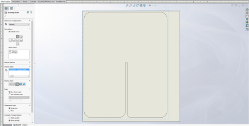
When finished, save your part, and create a drawing from the part. When asked, do not select any format by either hitting “cancel” or adjusting the page dimensions to fit your part (we want a plain sheet with the part on it). If unsure about dimensions, they can be changed later by right-clicking the sheet in the menu on the left, and selecting “properties”.
Drag the appropriate profile onto the sheet, and check the scale is set as 1:1. Once satisfied with the placement of the view on the sheet, save your drawing (save as .slddrw), and then save as a .dxf file.
Working in Inkscape:
Now open Inkscape, and open your .dxf file. Inkscape will prompt for a scaling method. If the drawing was in millimeters, we may choose “Manual scale” with a manual scale factor of 1.0. If the drawing was in inches, I've had the most success by choosing “Read from file” (millimeters is usually safer).
We can also use other units, but the “Manual scale” option will assume whatever units given are in millimeters. The scale factor we input corrects for the units to be in millimeters. For example, if my part is created and exported as a .dxf file in meters, then the scale factor would be 1000.0.
If your SOLIDWORKS version is a student edition, you will have to delete the text that appears in the drawing at the bottom. Afterwards, I would go to File > Document Properties (or Shift+Ctrl+D), and expand “Resize page to content”, then click “Resize page to drawing or selection”.
This will shrink the page to fit around the drawing. From here select all (Ctrl+A) and use Object > Fill and Stroke (or Shift+Ctrl+F) to bring up the Fill and Stroke dialog.
With the whole drawing still selected, several colors can be selected for cutting (mentioned in the manual linked above), but my preference among these is aqua. The easiest way to change the color of the stroke is by holding shift, and clicking the aqua tile in the bottom of the window.
Click on the “Stroke style” tab in the “Fill and Stroke” dialog. Finally, using mm as your unit, change the width to 0.010. Your image may seem to disappear, but it is still present (zoom in to see the lines).
It is good practice to save your work now as an .svg file to avoid problems later, and to allow quick repetition.
Finally, print from Inkscape using the Full Spectrum Engineering Driver.
Cutting
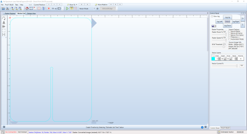
Your image will be loaded into RetinaEngrave3D. Click on the “Vector Cut” tab to view the results.
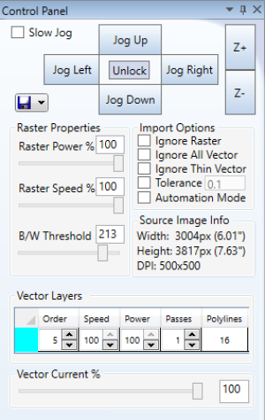
In addition to raster and jogging controls, the control panel on the right allows the operator to change vector cut preferences. When using additional colors, there will be multiple vector layers that each have their own settings.
Below is an explanation of the vector controls.
- Order: Decides the order in which layers are cut; the laser will cut in numerical order from 1 to 7.
- Speed: This is a percentage of the maximum speed that the laser will cut at (lower speeds yield deeper cuts at the same power)
- Power: This is a percentage of the laser's maximum power output and specifically controls the PWM frequency of voltage delivered to the laser.
- Passes: The number of passes over a given layer. The laser will not run backwards to repeat a pass; it returns to the beginning of the cut and completes it.
- Polylines: Indicates number of polylines included in the given layer. This cannot be changed, but may be useful when the expected number of polylines is known and the shown number is different. There could be two or more lines in the same position, which will result in multiple unintended passes over the same line.
- Vector Current %: This is a percentage of the laser's maximum current. This in combination with the power setting can be adjusted to cut what would normally ignite, such as paper.
Using controls learned in the introductory tutorial, position the laser to cut where it should. The perimeter trace function works the same in both raster and vector operations.
When satisfied, double check that RetinaEngrave3D is in vector mode, and click the play button, or press G to begin the cut.
The vector cut will not begin immediately like a raster engrave. The image will be converted so that the laser can follow the lines, and after a few seconds the laser will begin to cut. This process will take longer the more complex the cut.
Final Words
This tutorial's objective was to have student understand the workflow of designing a part to be cut by the FSL Pro 36×24 laser cutter.
Speculating future work derived from this tutorial, you may consider using the “Raster then Vector” feature included in the RetinaEngrave3D software, as well as the features offered by the “Design View” tab. Both of these can be easily navigated by someone familiar with raster engraving and vector cuts. These are covered very concisely in the manual.
For questions, clarifications, etc, Email: [email protected]


