Baja Buggie Tutorial
<html> <Title>Make Living Baja Buggie Tutorial</title> <p><b>Keywords:</b> Baja, Buggie, Mini, Living Room, Channel, Radio, PWM, Duty Cycle, Circuit, Transistor, MOSFET, Diode, Digital, Analog, Pin, pulse, serial, Perf Board</p> <p> <center>
<p></html>{{dylanw:hyundai-genesis-disassemble.jpg}}<html></p>
<p>Picture compliments of <a href="http://www.treehugger.com/cars/the-car-an-anatomical-journey-video.html" target="_blank">http://www.treehugger.com/cars/the-car-an-anatomical-journey-video.html</a></p>
</center> <p> The photo depicts the complexity of this project that appears to be extremely straightforward and quick to complete, which allows one to understand the underlying complexity of this project. The big picture problem is that radio controlling an object requires knowledge and skill in multiple fields of engineering and manufacturing. Solving this partially or completely is important because these skills form the basis for controlling almost any device in the current technological paradigm. This tutorial shows you how to build a Living Room Baja Buggie first presented in Volume 14 of Make Magazine and takes approximately 32 hours to complete. <br> <br> <br> <a name=“Motivation and Audience”></a> <H3>Motivation and Audience</H3>
This tutorial's motivation is to guide people new to remote control through the process of wireless control utilizing off the shelf radio control. Readers of this tutorial assumes the reader has the following background and interests: <ul>
<li><font color=“green”><b><i> Know how to read a circuit diagram/look at a circuit, and construct it</i></b></font>.
<li><font color=“green”><b><i> Also know how to program and utilize the analog features on the Arduino </i></b></font>
<li><font color=“green”><b><i>Know how to crimp and house 0.100" (servo) connectors </i></b></font>
<li><font color=“green”><b><i> Desire to learn how to interface a duty cycle signal to a PWM signal </i></b></font>
<li><font color=“green”><b><i> In addition, would like to use an oscilloscope or other measurement method to find the electrical charactristics of a circuit </i></b></font>
<li><font color=“green”><b><i> Also interested in learning how to RC practically anything </i></b></font> </ul> <p> The rest of the tutorial is presented as follows: <UL> <LI><a href=“#Parts”> Parts List and Sources</a> <LI><a href=“#Construction”> Construction</a> <LI><a href=“#Programming”> Programming</a><LI><a href=“#Final Words”> Final Words</a> </UL> <p> <a name=“Parts”></a> <H3>Parts List and Sources</H3>
US-based vendors to obtain material to complete this tutorial include Amazon (<a href=“http://www.amazon.com” target=“_blank”>http://www.amazon.com/</a>), Jameco (<a href=“http://www.jameco.com/” target=“_blank”>http://www.jameco.com/</a>), Digikey (<a href=“http://www.digikey.com/” target=“_blank”>http://www.digikey.com/</a>), and your local hardware store. <p> To complete this tutorial, you'll need the following items (in table below): <table width=“900” border=“5” cellspacing=“3” colspec=“L20 L20 L20 L20 L20 L20”>
<tbody>
<caption align="top">
TABLE 1: Parts needed to build a Living Room Baja Buggie
</caption>
<tbody>
<tr>
<td width="667">PART DESCRIPTION</td>
<td width="218">VENDOR</td>
<td width="122">PART</td>
<td width="104">PRICE (2013)</td>
<td width="41">QTY</td>
</tr>
<tr>
<td>Tamiya 70112 Buggy Kit (or other small toy buggy kit complete with motor)</td>
<td>Amazon</td>
<td>B002DR3H62</td>
<td>$23.49</td>
<td>1</td>
</tr>
<tr>
<td>Wireless Camera and Receiver Set</td>
<td>Amazon</td>
<td>B000JCQKVM</td>
<td>$35.12</td>
<td>1</td>
</tr>
<tr>
<td>Monitor or VGA Headset with Composite Video Input (or input compatible with wireless camera and receiver set)</td>
<td>Amazon</td>
<td>BWCMO363</td>
<td>$20.30</td>
<td>1</td>
</tr>
<tr>
<td>Arduino Uno (or other controller board with 3V Power and PWM input and output pins)</td>
<td>Amazon</td>
<td>B006H06TVG</td>
<td>$21.95</td>
<td>1</td>
</tr>
<tr>
<td>4-Channel Radio Transmitter</td>
<td>Amazon</td>
<td>B004NZGF98</td>
<td>$69.00</td>
<td>1</td>
</tr>
<tr>
<td>4-Channel Radio Radio Reciever (that can pair with the transmitter)</td>
<td>Amazon</td>
<td>B007TJU5KU</td>
<td>$30.59</td>
<td>1</td>
</tr>
<tr>
<td>Servo Motors</td>
<td>Amazon</td>
<td>B0006O3XEA</td>
<td>$11.41</td>
<td>2</td>
</tr>
<tr>
<td>9V Battery</td>
<td>Amazon</td>
<td>B00003IE4E</td>
<td>$4.20 for 2</td>
<td>2</td>
</tr>
<tr>
<td>9V Battery Connector</td>
<td>Amazon</td>
<td>B00CBSDFH4</td>
<td>$0.59 for 5</td>
<td>1</td>
</tr>
<tr>
<td>9V Battery Adapter for Arduino</td>
<td>Amazon</td>
<td>B005D65LEG</td>
<td>$2.83 for 2</td>
<td>1</td>
</tr>
<tr>
<td>0.1mm 1 Row, 3 Pin Housing</td>
<td>Digikey</td>
<td>609-2340-ND</td>
<td>$0.69</td>
<td>3</td>
</tr>
<tr>
<td>0.1mm Pin Crimps</td>
<td>Jameco</td>
<td>104480-8</td>
<td>0.15</td>
<td>9</td>
</tr>
<tr>
<td>22 AWG Wire</td>
<td>Jameco</td>
<td>734311</td>
<td>$10.95</td>
<td>1</td>
</tr>
<tr>
<td>MOSFET Transistor</td>
<td> </td>
<td> </td>
<td> </td>
<td>1</td>
</tr>
<tr>
<td>Directional Diode</td>
<td> </td>
<td> </td>
<td> </td>
<td>1</td>
</tr>
<tr>
<td>Various Screws</td>
<td>Local Hardware Store</td>
<td>N/A</td>
<td>Varies</td>
<td>Varies</td>
</tr>
</tbody>
</table> <br> <p> <p><a name=“Construction”></a> <H3>Construction</H3>
This section gives step-by-step instructions along with photos to contruct and run the buggie.
<H4>Step 1</H4>
<p>Build the car's body as directed by the kit's instructions. Leave out electric components like the battery holder and like, we will be replacing those parts.</p>
<p>Your car should look something like this:</p>
<p><center></html> <html></center></p>
<h4>Step 2</h4>
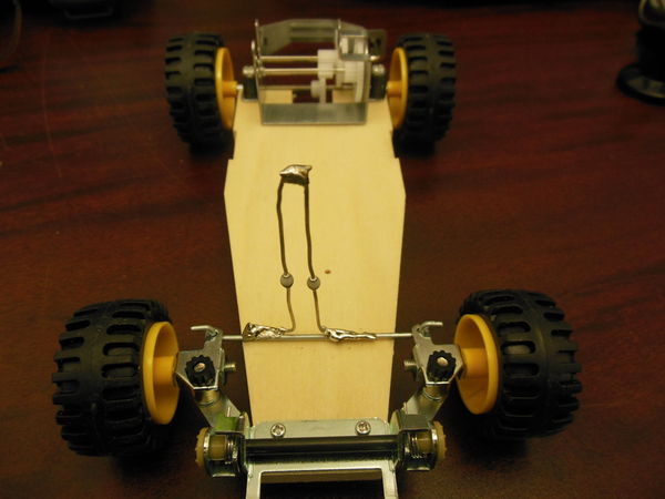
<p>Solder a heavy guage wire in the shape of an Ω (ohm) to the steering bar of the car to allow for a servo to be used to remotely steer the cart.</p>
<p>The cart should look like this after the wire is attached:</p>
<p><center></html>
 <html></center></p>
<p> </p>
<H4>Step 3</H4>
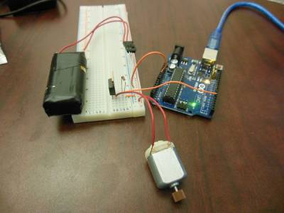
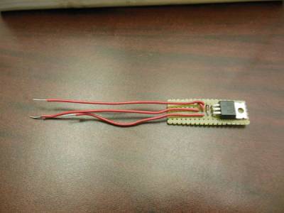
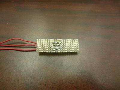
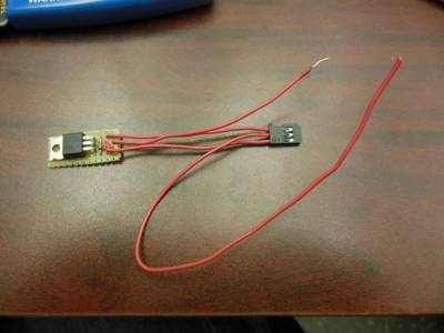
<p>Create the speed controller circuit shown below, test with the Arduino creating a PWM signal to ensure that circuit is functional before soldering.</p>
<p><center></html>
 <html></center></p>
<p><center></html>
 <html></center></p>
<p> </p>
<h4>Step 4</h4>
<p>Pair the transmitter with the reciever, use this to test the servos.</p>
<p> </p>
<H4><strong>Step 5</strong></H4>
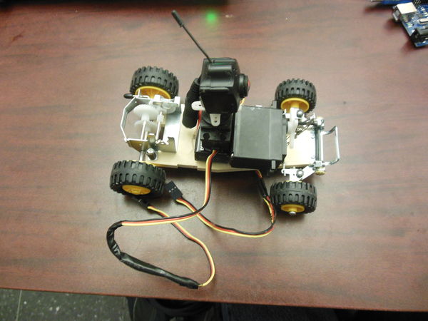
<p>Attach the two servos to the cart using the 9V batteries as a vertical offset. Also attach the camera to the top of the horizontal actuating servo.</p>
<p>One 9V battery is used to power the camera, while the other battery is used to power the control circuitry.</p>
<p>The cart should look like this after you attached everything:</p>
<H4><center></html>
 <html></center></H4>
<H4> </H4>
<H4>Step 6</H4>
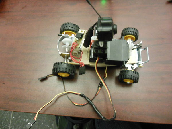
<p>Attach the motor with control circuitry.</p>
<p>The cart should look like this now:</p>
<p><center></html>
 <html></center></p>
<p> </p>
<h4>Step 7</h4>
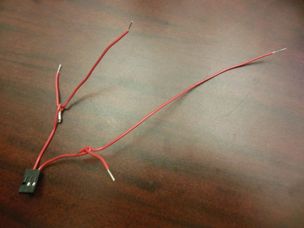
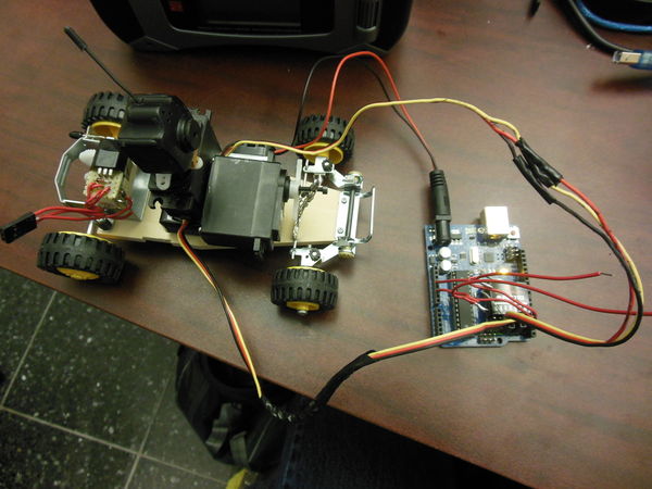
<p>Power the reciever with the 3.3V pin on the Arduino using the wiring shown below, plug in the servos and calibrate.</p>
<p><center></html>
 <html></center></p>
<p>Cart should look like this now:</p>
<p><center></html>
 <html></center></p>
<p> </p>
<h4>Step 8</h4>
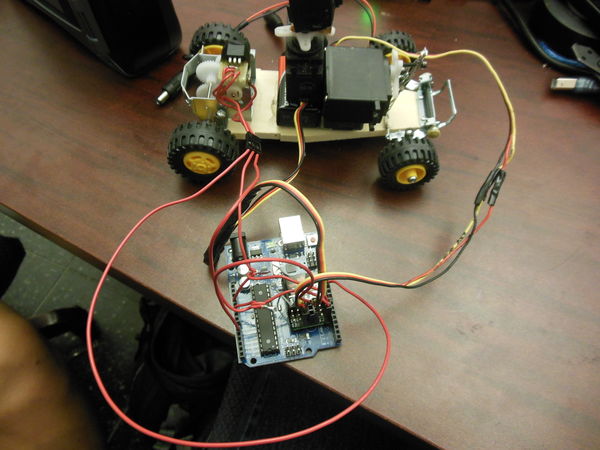
<p>Program the Arduino using the duty signal from the reciever. Using the wire shown below:</p>
<p><center></html>
 <html></center></p>
<p>Code is attached below in the programming section.</p>
<p>The circuit should look something like this now:</p>
<H4><center></html>
 <html></center></H4>
<H4> </H4>
<H4>Step 9</H4>
<p>Power everything and see the cart work!</p>
<p>Here is the finished product:</p>
<H4><center></html>
 <html></center></H4>
<H4> </H4>
<p>
<a name="Programming"></a>
<H3>Programming</H3>
The source code to run the buggie using the Arduino IDE is provided below: <hr size=4 width=“90%”> <center> <font size=+1><b>To be compiled with the Arduino IDE</b></font><br> </center> <PRE> </PRE> <p>const int signalPin = A0; pin where duty cycle of reciever is inputted<br> const int outputPin = 11; pin where pwm signal is outputted<br>
float duration;<br>
float pwmsignal;</p> <p>void setup()<br>
{<br>
  Serial.begin(115200); //serial monitor setup</p>
<p>   pinMode(signalPin, INPUT); sets pin as input<br>   pinMode(pwmsignal, OUTPUT); sets pin as output<br>
}</p>
<p>void loop()<br>
{<br>
  duration = pulseIn(signalPin, HIGH); //detects duty cycle</p>
<p><br>
  pwmsignal = 924.375-0.6375*duration; //calculates equivalent PWM signal, you will need to calculate this signal using this program<br>
  if (pwmsignal>255) //saturation of signal limiter<br>
  {<br>
    pwmsignal=255;<br>
  }<br>
  if (pwmsignal<0) //negative signal limiter<br>
  {<br>
    pwmsignal=0;<br>
  }<br>
  analogWrite(outputPin, pwmsignal); //outputs PWM signal on pin 11<br>
<br>
  Serial.print(duration); //serial output of length of duty cycle<br>
  Serial.print(", ");<br>
  Serial.println(pwmsignal); //serial output of calculated PWM output<br>
  delay(100);<br>
}</p>
<hr size=4 width=“90%”>
<H4>Duty_to_PWM.ino Fuller Code Description</H4>
<p>The Duty to PWM converter operates as follows:</p> <p>The Arduino controller board detects and measures the length of the duty cycle. From there, the Arduino calculates what the equivalent PWM signal to output to the motor, and outputs it through the output pin. <a name=“Final Words”></a> </p> <H2>Final Words</H2> This tutorial's objective was to learn how to utilize a duty cycle to control a motor via PWM. Complete the programming section and step 3 in the construction section for a duty cycle to pwm motor controller circuit. Once the concepts were conveyed the reader could control any DC motor with a duty cycle control signal, which is what is created by most transmitter/receiver sets. <p> Speculating future work, derived from this tutorial, includes creating a bi-directional duty cycle to pwm motor controller (so motor could move in forward and reverse). In the big picture, the problem of creating a DIY mini Baja Buggie and duty cyle to motor control circuit can be solved with this tutorial. <p> Click <a href=MAILTO:jamesysato@gmail.com>here</a> to email me <p> </body> </html>
