Table of Contents
Measuring Odometry with an Optical Mouse
The aim of this project was to accurately measure odometry using a standard optical mouse and an IMU. It is believed that using an optical mouse in this way is beneficial because even when the vehicle is slipping it will still be possible to measure odometry accurately.
Interfacing the mouse
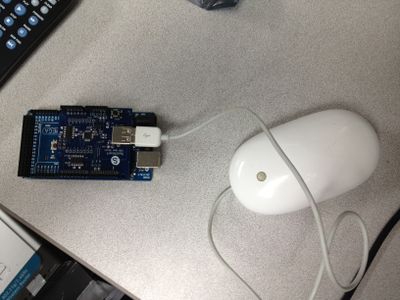
The mouse was attached to an Arduino mega using a SainSmart USB host shield. A library was downloaded from the usb host shield git hub page. Several Mice were then tested an unknown brand gaming mouse, a corsair gaming mouse and an Apple Mighty Mouse. Though the gaming mice had high precision they had non-linear output with velocity. All three mice worked on desktop, tile floor, carpet and sheet metal. The Apple mouse was selected because of it's linear output and it's ability to function on sheet metal.
The mouse output was then calibrated to meters and summed to show absolute position. The mouse was then moved around a flat surface in various ways, without rotation, and moved back to the initial position. The error in the original position was consistently +/- 1 cm in the x and y direction over a approximately a 1 meter movement. The optical mouse also has the advantage to be able to measure odometry even when the vehicle is slipping.
Creating the mouse mount
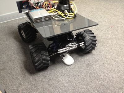
When mounting the mouse it is important that is can rise up and down over uneven terrain. However, it is also important that the mouse stay aligned with the vehicle's reference frame so a rigid structure was needed.
The bracket was made of an aluminum tube attached by a hinge to the vehicle and another hinge attaching it to the mouse.
Installing the IMU
An MPU 6050 was ordered from amazon.com and wired on breadboard. A library was found to accompany it. The library was used to read out orientation data in the form of yaw pitch roll.
The code
A dedicated Arduino mega reads and processes the data from the mouse and the IMU. This was done because there can be no delays between mouse data reads. The main control Arduino has mandatory delays to operate the sonic rangefinders.
The Mouse measures change in position in the local reference frame. The data from the mouse, (dx,dy), is then converted to the global reference frame using the data from the IMU. The now global (dx,dy,dz) vector from the mouse is then added to the last known position. The position measuring Arduino then sends the global x,y,z position to the main control Arduino.
Results
Initial 2 dimensional test
Another 2D test after code for 3 diminutional movement was added.
In both 2d cases the vehicle's final position was within 50 cm of the expected position over at least a 15 meter corse.
A 3D motion test in the ductwork assembly
The elevation of the beginning and the end of the test track are at the same elevation. As you can see this is reflected in the odometry readings.


