Table of Contents
Co-Axial Helicopter with IR Elevation Control
Introduction
This is the project I am working on in order to better prepare myself for working with Dr. Tadokoro in Japan next fall. I will be recreating the project found in this article: mcubasedaltitudecontrol.pdf in order to learn from the experience.
GantChart
Updates
2/11/13
Created first plan for project, which fell through because I was sick on the weekend I was planning on coming. Instead I just read up on the article and did some research on hardware, IR, and building a circuit.
2/22/13
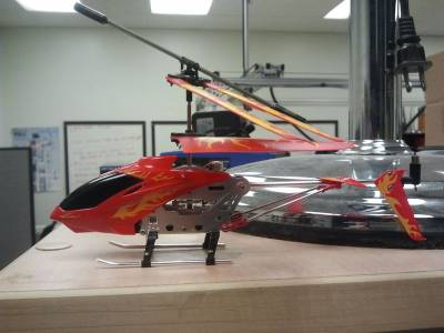
Today I came into the lab and worked on the Dr. Oh's coaxial helicopter (Syma 107RS). I attempted to turn on the heli and controller and while the helicopter turned on, the controller didn't. I tested 3 sets of batteries in the controller and the controller still didn't turn on. I decided to take apart the controller and see if there was a broken circuit/wire I could fix. However, there was no obvious problem so I had to instead order another helicopter online. After speaking with Chris, I determined that I should get hardware that will make it easier to control the heli using an arduino. So I purchased another Syma 107, a radio controller that can be used with a 3.5mm audio jack (built for smartphones, but I can control it with an arduino and an audio jack connected via a bread board. I also purchased IR LEDs and IR Detectors to control with the Arduino. Here are the images I took of previous Syma and its controller.
3/2/13
Tested the Yellow Syma 107 Helicopter that came in the previous week. The controller works with the Red Syma helicopter and it flies well. It is difficult to fly the yellow helicopter and it constantly translates to its left while it is flying, so it is a difficult to simply have it hover in the air. However this will not be a problem once it is restricted to only vertical movement. However no other parts came in the previous week so all I could do was test the helicopter.
3/16/13
I downloaded several android apps that work with the audio jack transmitter. However none of them worked on the syma 107, even the one designed to work with it. I attempted to use the code I had found online to signal the Syma 107 with the Arduino program I had written, but that didn't work either. So instead I dissembled the old transmitter and unsoldered the potentiometers in preparation for using it with the arduino.
3/19/13
I tested the android transmitter with Chris's phone an it worked, proving that it wasn't designed for my phone despite claiming to be. I applied power across the old transmitter's circuit board to test if it still worked - It did. I soldered wires onto the place where the potentiometers were to provide input digitally from the arduino. Hopefully tomorrow I will be able to fly the helicopter with the hacked transmitter tomorrow. I also tested the circuit with visible spectrum LEDs that I had constructed to see how the pulses looked to the heli.
3/20-21/13
I spent these days testing the Infrared LED and attempting to send a signal to the SYMA helicopter from my arduino. When testing my first program I realized that it didn't send the correct signal to the SYMA. After speaking with Rob, I decided to test the signal being put out by hooking up an oscilloscope to a infrared receiver and examining the signal being sent from the real transmitter. After seeing how the signal changed, I decided to look online to see if anyone had decoded the signal that I could borrow.
4/1/13
The program I have written is able to set the throttle on the Syma 107.
4/2/13
I started writing a program that would make the helicopter's throttle rise and stop at a certain throttle to simulate what the program would do. First it would make the helicopter rise and then stop the helicopter when it had reached the height desired.
4/4/13
I realized that the helicoper needed something to prevent it from traveling in a direction other than up and down. So I decided to start working on a parallel bar system. I started working on this device in the machine shop by taking some recycled wood. However I quickly realized that the wood split and splintered and became unable to serve the purpose I needed. I decided that I would need another material.
4/6-7/13
I've been working on an autocad file to laser cut some parts to make the parallel bar system in the Hess machine shop. I've also been working on the program that will take a height entered and make the helicopter rise to the height and attempt to maintain it's height based on some other factor.
5/17/2013
I tested the payload of the Syma 107 in order to test how much additional electronics it can lift without affecting it's thrust too much. I determined this to be around 35-40g. Although this may reduce the thrust, the helicopter needs to be weighed down a little in order to track the its height during flight.
5/27/2013
This week I worked on a new AutoCad file in order to cut the pieces that I will assemble into a parallel bar system. The issue is that because of various projects, exams and midterms, and work due this week in class, I was unable to enter the Hess lab in order to laser cut the parts (after speaking with RJ earlier, he recommended using the Hess lab instead of the DASL CNC machine for the parts). I will go into the lab on Tuesday to cut the parts. I will still work on the next step in the project this week in order to keep on track as it does not rely on the parallel bar system to be constructed.
5/30/13
I cut the parts for the helicopter boom on Tuesday and assembled it today. Here is a video of it moving.
6/2/13
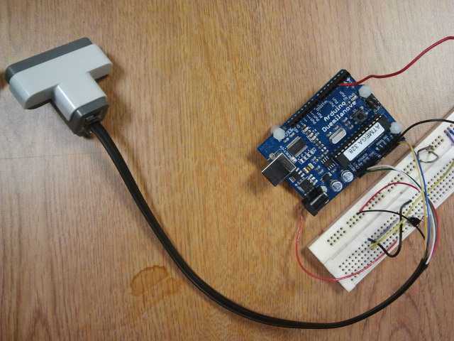
This past week I assembled the helicopter boom an the helicopter. I have also created a circuit to measure the height of the helicopter by attacking an ultrasonic sensor to the opposite end of the boom pointing at the ground. Since the ultrasonic sensor will be aiming at the ground and will always be parallel, the height can be determined pretty easily. Also, since the distance from a table to the floor is already a fair distance, there will be no issues with the ultrasonic being too close to the surface it is determining distance to. This following week I will attempt to write the learning algorithm.

Ultrasonic connected to the arduino and values can be read off of it
Here is the arduino file that I use to send data to and from the ultrasonic to receive the distance measurement.
6/8/13
This past week I was working on the algorithm to read the ultrasonic values and learn the correct IR signal to send to the helicopter to make it rise based on the reading from the Ultrasonic sensor. I have been able to get the signal to change and raise the heli, however additional testing is still needed. The following video shows the system in action.
6/19/13
I have taken a break to take final exams for the past term. Afterwards I had to travel home to Chicago. I took my components with me in order to continue working. I have been coding, however, the parallel bar system was broken on the trip over. I am still tweaking my code however, when I return to Philadelphia I will cut another piece to replace the one that broke and finish testing. I have compiled a list of all the part necessary, where to purchase them and their costs for this project. I have also added a pdf drawing of the parallel bar components and have listed their lengths.
Parts List
| Item | Quantity | Price | Supplier |
|---|---|---|---|
| Helicopter | 1 | 18.95 | Amazon |
| IR LED | 1 | 0.75 | Adafruit |
| Arduino UNO R3* | 1 | 29.95 | Adafruit |
| Cast Acrylic* | 12in x 12in x .236in | 11.95 | Adafruit |
| NXT US Sensor* | 1 | 21.99 | Amazon |
| NXT Connector Cables* | 1 | 24.59 | Amazon |
| Sharp GP2D02 IR Sensor* | 1 | 12.50 | Mark III Robot Store |
| Superglue | 1 | 5.64 | Amazon |
| Motorola 1N4001 Diode* | 1 | 0.18 | Digi-Key |
| Total | 126.50 |
*These components were found in the lab, a place to purchase them is provided.
Parallel Bar Components
Each piece is cut multiple times to have backups in case they break.
The large t-shaped parts are glued to the helicopter's landing gear to attach it to the boom. Both parts can be glued on opposite sides for greater stability in balancing. Superglue is a good choice glue.
| Component | Dimensions |
|---|---|
| Parallel Bar | 20mm x 300mm |
| Connector Pieces | 20mm x 45mm |
| End Pieces | 20mm x 85mm |
| T-shape (bar) | 20mm x 100mm |
| T-shape (narrow piece) | 2.5mm x 45mm |
| Hole sizes | 2mm |
| Distance between holes | 25mm |
| Contour radius | 5mm |
6/28/13
When I returned to campus I found that the laser cutting lab was shut down for the summer. As a result, I chose to directly super-glue the helicopter to the helicopter boom instead of gluing the landing gear to the helicopter boom. I proceed to test my code. I found that the ultrasonic sensor was simply not outputting accurate enough values for the program. As a result I decided to quickly change the NXT Ultrasonic sensor to a Sharp GP2D02 IR distance sensor. It was fairly simple to set up this sensor and integrate it into my program. I used a library by Joseph Rollinson and built off of the example code provided. The GP2D02 values correspond to distance in the following way from this datasheet.
I then proceeded to test my program in order to get readings. After tweaking for a bit, the ending program was able to get the readings needed in order to begin improving on its runs each time.
Final Circuit Design
Algorithm Description
Code is here: Co-Axial Helicopter with IR Elevation Control Final Code
The way the algorithm works is it is first inputted value for the height that it needs to achieve. It converts this to a signal to look for from the GP2D02 with a bit of wiggle room. The algorithm then proceeds to randomize a value for the throttle. After five seconds it records a fitness value (based on the absolute distance between the height needed and the height achieved scaled by the distance between the height needed and the min or max value that can be achieved on the boom.) it and associates it with the throttle value and a run number. It then reruns the algorithm and checks the previous fitness value, if it is an improvement, it overwrites it. If it ever achieves a perfect fitness value it stops completely. However this is unlikely as I kept the noise in the values. After 30 runs I stopped because I judged that the algorithm had produced as good of a pulse it could to lift the helicopter to the height needed (the fitness value was close to what was needed but had remained constant). The following Youtube link shows the resulting flight of the helicopter. The algorithm needs to be rerun each time with a new starting value.
Final Project Video
Reflection
This was a very difficult project for me and in the end ruined my image of myself. I thought too highly of myself when I first started creating my gantt chart. I thought it would only take me two weeks. The project didn't seem difficult, I had done similar things before. However, weeks soon turned into months. Pretty soon it became apparent that I did not have the knowledge necessary to decode signals, construct circuits and develop the programs. I felt this was supposed to be a learning experience, so for a long time I chose not to take the simple way out and search if someone else had already decoded the signals. This was my main problem. I did not have the skills or understanding to accomplish this on my own and even asking other members in the lab to teach me how to do things use the oscilloscope to find the signal being sent to the helicopter didn't help me too much, because the next step was decoding it. Usually when I work on my own projects I tend to build on what other people have already done, but In my head I had decided that like a true researcher, I needed to find this information from scratch. I could hardly say I'd learned anything if I just Frankenstein together other peoples work. Asking for help was difficult because I asked often and felt bad for needing to ask so often to accomplish this task. On top of all that I could not handle the stress of everything I had to do I was juggling a maximum class load, attempting to raise my GPA, taking some of my classes as honors options, learning more Japanese for my quickly approaching trip to japan for a year and learning how to live alone. As deadlines kept coming up and I hadn't yet finished, I had to come to the grim realization that I'm not capable of doing the true research aspect like I wanted. In order to finish the project I chose to start finding what other people had already done and assimilating their work so that I could finish. Often I wouldn't understand what was being done and would have to guess or search online for a better explanation or ask a lab member for their help, but I sometimes I couldn't find a better explanation so I had to experiment with different constructions of a circuit or code until I could get something that came close to what I needed. The parts that came easiest for me was coding the Arduino and combining what other people had done before me. This project seemed easy in the beginning, but in the end I have to just realize that I'm most likely not capable of experimenting for data, estimating my own abilities, planning a schedule or adhering to a work schedule I had already made. It's making me question if research is a viable career path despite that being my dream for a long time now. In addition to this I managed to lower my GPA, nearly fail a few classes and get dropped from the honors college and ruin my chance for a BS/MS. The bright side is that I now know what I need to work on. I know what I am lacking and how I should proceed with future projects. I also learned a lot. Many of the things that I struggled with understanding for weeks, I eventually reached breakthrough on. I now have a good understanding of how to send signals through IR, how to use the I2C protocol, how to use an oscilloscope to examine signals. Possibly after a few more years of school, classes and projects I will have the skills I found myself lacking. It is a good thing I am still an undergraduate student as I have a few more years to learn these skills.


