Table of Contents
Building an FPV Quadrotor
Edited With Help By: Micheal Salinas
Date last modified on: 06/30/16
Keywords: Tutorial on how to put together a FPV 250 quadcoptor
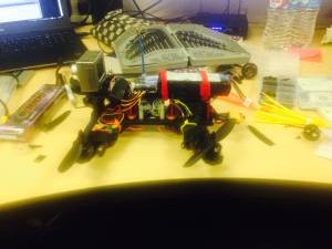
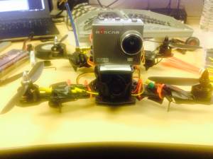
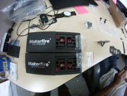
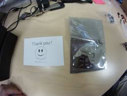
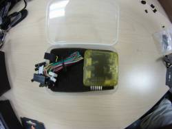
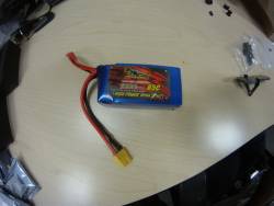
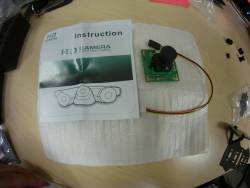
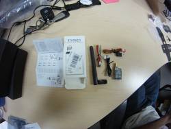
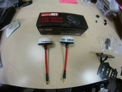
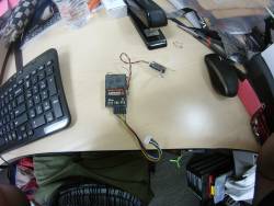
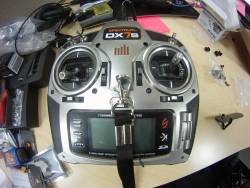
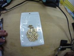
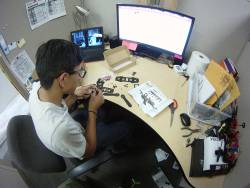
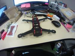
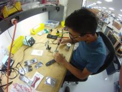
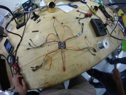
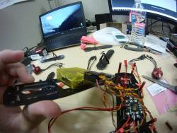
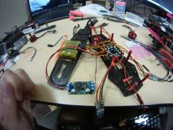
The photos above depicts what your first completed FPV 250 quadcoptor setup might look like. This tutorial shows you how to find, buy, and connect the various hardware and software needed to fly a quadcoptor manually with FPV. This will take approzimately 10-15 hours.
I would suggest that you should first read through this tutorial then start working on the build. This will help make your build time quicker with less problems because you already know what is coming next.
Motivation and Audience
This tutorial's motivation is to educate readers on the hardware and shareware necessary to get a 250 fpv quadcopter working. Readers of this tutorial are assumed to have the following background:
*Has experience in soldering
*Has basic knowledge in electronics
*Knows how to problem solve
*Has already flown a quadcopter in a simulator
If you haven't flow using a simulator go here first.
The rest of this tutorial is presented as follows:
I will put a sub-section called problem solving when I run into a problem, and explain how I fixed it in each section.
Parts Lists and Sources
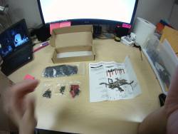
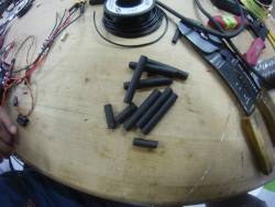
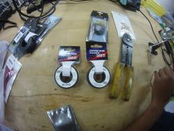
I will link the parts to amazon links but if you want to find similar products at other vendors please check these other websites. Most of the items on this list can be found in the lab already. Please search for them first then purchase what couldn't be found. Use the photos to help identify items.
Equipment List
These are the equipment necessary to construct the FPV quad. The listed items will be in the lab so please locate them and use them.
DO NOT FORGET TO PUT THE EQUIPMENT BACK AFTER USE.
Construction
This section gives instructions with photos on how to build a quadcopter with FPV capabilities. Because there are so many different components you could possibly have I will try to keep this tutorial from being too specific on what I had. The construction will follow this work flow:
- Frame
- Electronics
- Mounting
Frame
There are a lot of different variations for frames. Thus the frame I used will probably not be the frame that you have. For the most part frame assembly is not hard. Look up or follow the instructions that come with the frame.
One tip I would give is to leave the top of the frame off, if possible. This will make installing the components inside much easier later on. The picture below is of my frame without its top on.
I would suggest that you start to charge the lipo battery you plan to use as you build the frame. This way it will be ready for you when you need it later. Make sure to 'balance charge' it to the appropriate voltage and amperage.
Please read this Battery Management wiki to learn how to manage lipo batteries if you haven't done so before.
Electronics
This part of the build will require that you solder wires to the PDB. If you do not already have experience soldering, have someone else in the lab teach you.
DO NOT SOLDER WITHOUT PROPER KNOWLEDGE!!! YOU CAN SEVERELY BURN YOURSELF OR SET SOMETHING ON FIRE!!!!!
This is how electricity from the battery gets to all of the components that need it. Solder the ESC's, camera power connector, and battery connector to the correct places. If you want anything else that needs power on the quad this is where you would connect it as well. Here are some pointers before you begin:
- Make sure that you are soldering the right wire to the spot. Each point is labeled with a + or - sign that indicates whether its a power or ground point. If it is not printed on the board look up the schematics of the board. Please do not mix them up as if can cause component failure (i.e. explosions and fires) if the polarity is backwards.
- Be careful of what you connect to it. The power distribution board will distribute the voltage equally among all of the components. Thus if your esc, camera, or any other items are not rated for the amount of voltage coming from the battery they could get damaged. If you need to connect an item that takes a lower or higher voltage than the battery you can use a voltage regulator like this one
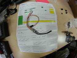
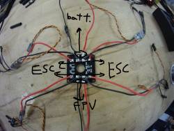
I will now guide you step by step on what and where to solder onto the PDB. Make sure that the red wire goes to power and the black goes to ground. Below is a reference picture to use for solder spots.
P.S. When I solder onto the PCB I put a blob onto the board first then melt the wire into it. I found that this makes the solder cleaner and less likely to fall off.
- First, solder on the power connector (female xt-60) for the battery and the fpv setup.
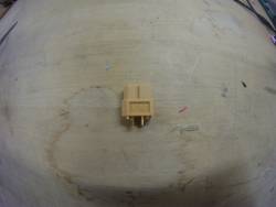
- Find red and black wires with a similar gauge to the power wires on the ESC's and solder one side onto the PDB at the front or back, as shown in the picture above. Then solder the female xt-60 (shown below) connector to the other end of the wires. Do not forget to put heat shrink on the solder points to prevent short circuiting (see picture below).
- Solder the female JST connector to the spot shown in the image above.
- Second, solder the ESC's power wires(shown below) to the appropriate spots (reference picture above).
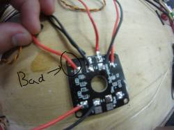
- Make sure not to cover the holes on the corners of the board. You will use them to secure the board onto the frame later on.
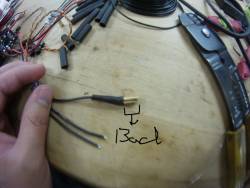
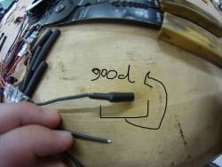
Now that you are done with the PDB it is time to solder the banana connectors onto the motor connectors on the ESC and motors. Make sure to keep which side is female or male consistent throughout, and do not forget to add heat shrink to prevent short circuiting. Images below show a good and bad heat shrink job for the female connector. We found if helpful to use the 'helping hands' to hold the connector and wire still while I soldered the two together.
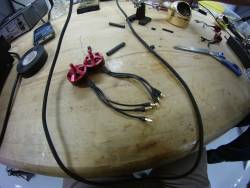
Once you are done soldering the connectors your motors should look like this. Notice that we used the male connectors for the motor. We only covered the part that will be exposed while plugged into the female connector with heat shrink.
Problem Solving
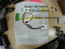
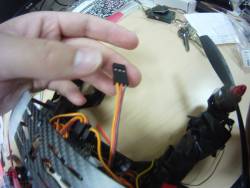
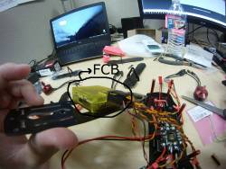
While soldering the ESC's we noticed that the flight controller board (FCB) connector only had two lines. Usually there are three lines on the FCB connector, one for signal, one for power, and one for ground. However in the two line variation we had there was only signal and ground. This meant that there was no power going to the FCB. After reading this blog post we understood what we had to do. Below are pictures of a 3 line connector vs. a 2 line connector.
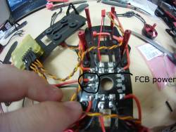
First we looked up the manual for the FCB (in our case a cc3d) and found out what voltage it is rated for. Since it was rated for 5v and our PDB outputs 12v we needed to put a step-down voltage regulator to power the FCB without frying it. The one in the pictures is one we had lying around and is overkill for our purposes. The link is to a more appropriate voltage regulator. We soldered the voltage regulator to open spots on the PDB and canibalized some single pin female jumper cable to connect the vout and ground from the voltage regulator to the FCB. Making sure to connect the power to the middle pin and ground to the bottom pin as the top is for signal.
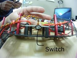
We tested it by plugging our battery in to see if the LEDs on the FCB would light up. During this we found out that there are switches to power and turn off the smaller spots we used for the FCB. Since the LEDs lite up and the FCB didn't explode we called it fixed and moved onto mounting everything to the frame.
Mounting
Now that you have all of the electronics figured out it is time to mount them onto the frame. You will mount the:
- PDB
- FCB
- ESCs
- Motors
- Controller reciever
PDB
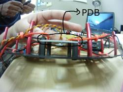
This should be placed in a central position of the quad where it is protected from impact. If the soldering is exposed it could allow for shorts or on impact (when you crash) it could come off.
Because the switches didn't allow the board to sit flat on the frame, and because the carbon fiber frame could cause a short on the board I used nylon spacers to raise it slightly (see image below). However because my screws weren't long enough to go through the whole frame I had to take it apart in order to screw the spacers on.
FCB
Usually I would want to mount the FCB above the PDB using mores spacers. However Because we failed to take off the cover that came with it (the pale yellow box) we decided to use double sided tape and stick it to the underside of the top piece (see image below). Make sure when installing that the arrow on the board is pointing forwards, and that the board is facing upwards. There is a gyroscope on the FCB that it uses to auto balance. If this isn't installed correctly the quad will be unable to fly (i.e. you will break a lot of props).
ESCs
Since these are soldered to the PDB there isn't a lot of play on where you can place the ESCs. Especially on the small frame of the 250. Depending on your frame the best place for the esc can differ but in our case we stuck them down, using double sided tape, on top of the arm they were closest to so that there was one ESC per arm. You can also use zip-ties or electric tape to do this. Then take the 3 pin connector and connect it back to the FCB. Please check the manual for your FCB because where you plug the ESCs in is different for each. For the cc3d it was from the top pins Front Left, Front Right, Back Right, Back Left, with ground on the right and signal on the left pin. Then the power pins we created went into one of the open pin slot with power in the middle and ground on the right. For now don't worry about the loose motor connectors, we will secure those down later.
Motors
The box that the motors came in should have also came with some screws, and maybe an allen-key. Don't lose these screws since you will be using them to screw the motor onto the frame. If they didn't come with an allen-key first find the correct allen-key to screw them in. Then check the mounting on the bottom of the motor, and see how it aligns with the mounting holes on the frame. In our case since the mounting pattern on the motor and the screw size were different from that of the frame we used a dremel to widen and elongate the mounting slots on the frame.
A tip I would give is to check which direction the propeller nut goes onto the motor. It will either go on cw or ccw. Reference an image of what direction the motors need to go (this is different depending on the frame type or number of motors) and mount the motors so that the direction the nuts goes on is the same direction the motor spins. This is to prevent the motor from spinning off the nut mid flight. Once they are properly mounted connect all of the motor connectors to the ESC, don't worry about order since it can easily be changed later.
Do not put the propellers onto the motors yet!!
Controller Receiver
Now it is time to connect the controller receiver to the FCB. Depending on what type of receiver and what type of board you get this will differ. If your board had the appropriate port for the reciever just plug it in, careful not to bend the pins inside. If it doesn't then you will have to find out where and how to connect them by reading the FCB manual or going to a forum. The cc3d has the appropriate port so this isn't much of a problem. Once connected find a spot on the frame to put secure the receiver (for me ususually on top of the frame).
Note: Please keep in mind that you will also have to put the battery,
Now if you want to you can put the top of the frame back on. But make sure the the usb mini port on the FCB is still accessible. You will be using that port in the next step.
GCS Setup
Congratulations, you are almost finished with making your first quadcopter! For the next step you will need these items:
- Quadcopter you have been working on
- (Depending on what FCB you have) A fully charged lipo battery
- Cable to connect the FCB to a computuer (i.e. usb mini to usb)
- Computer with a GCS program installed
- Controller and controller reciever
At this point you will need to either find a computer with a Ground Control Station (GCS) software on it or download one. The one we used is Open Pilot GCS. Unfourtunately this GCS is no longer supported and is not available for download online. I would suggest that you use Mission Planner instead. Though there are differences between the two, the setup wizard is similar for both. Even if there are differences, as long as you follow the directions closely there should be no problems.
Before downloading any GCS software please check which boards the software supports. Sometimes an earlier version supported a board, but the newest version dropped supports. I had this issue with my cc3d and Open Pilot where I had to download an older version that supported the board.
Follow the vehicle setup wizard to configure your quadcopter. Then after your done go onto the controller setup wizard.
Now it is time to tie/tape down all of the loose wires on the quadcopter down. Use what ever method you want to make sure that any wires aren't in danger of getting eaten by the propellers or shorting. Then it is time to put the propellers on.
Before putting propellers onto the motors and flying it is important to know that propellers have cw and ccw directions as well. You will want the high end of the prop to move around scooping up air and pushing it down. This lets you know whether it is cw or ccw. Put the cw propellers on the cw motors and ccw propellers on the ccw motors.
Secure the battery to the frame using double sided tape or velcro zip-ties, and done!
Now it is time to take the quadcopter for a test flight! Tip: Be vary, vary, vary easy on the throttle. The last thing you want is to explain why there is a hole in the ceiling.
FPV Setup
Now that you have finished the quadcopter aspect you have to create the FPV setup to create an FPV quadcopter!
These are the items you will need for this part:
- The quadcopter you just finished
- A video camera
- A video transmitter
- The corresponding wires to connect the camera to the transmitter to a battery
- A video reciever (inside the FPV goggles)
- A video monitor (the FPV goggles)
If you bought the bundle set I put as the link you will not have any issues with compatibly however if you buy the items separately this won't be as easy.
- 1) Figure out how you will power the transmitter and the camera. The set that I linked earlier comes with a battery. However there are pros and cons to this. It is great if you want to keep the FPV setup independent of the quadcopter setup. This might be usefeul if your quadcopter runs out of battery and you lost physical sight of it. You can use the FPV camera to locate it by seeing what is close to the quadcopter. However this adds extra weight and is another point of failure. Extra weight can cut flight time and if the FPV battery dies out midf-light and your don't have a physical visual of the quadcopter you are flying blind. For a first time setup I would recomend using the battery since it is much easier and quicker to do. But after maybe 1 or 2 flights to switch over to using the PDB (remember the JST connector we soldered?) to power it.
- 2) What you do next will depend on what you decided.
- If you decided to use the battery connect everything on a table and test the equipment. Toggle the channel finder to get the video feed and check that everything is working. Do not turn on the goggle or video transmitter without connecting the antennas to them first. They will explode if you don't
- If you decided to power them from the PDB find out how you will power them.
- Some video transmitters have a v-out out to the camera while others don't. If it does check to see that the voltage coming out of the transmitter is what the camera can handle. If it isn't either buy a voltage regulator or another camera/transmitter that can handle/give the appropriate voltage. Once done test everything out on a table to make sure that it works.
- If the transmitter doesn't have a v-out then you will have to create a wire that can supply the appropriate voltage to both the transmitter and the camera. This will probably involve some kind of butchering of wires, and soldering other wires together to get the intended result.Once done test everything out on a table to make sure that it works.
- 3) Now all that is left is to put it on the quadcopter. Find a spot on the front end of the frame to mount or secure the camera to. Use zipties, electric tape or double sided tape to do this. Then find other places to put the rest of your setup so that it isn't interfering with the rest of the setup.
- 4) Time to fly using FPV! Be vary cautious and double check your surroundings first.
DONE!!
Once you have gone through all of these steps, you now have a working FPV quadcopter!
Now go outside to a relatively large park with a couple spotters to let you know when someone is close by and crash it!!!
In las vegas there is a quadcopter racing community, if you are interested in this check them out on facebook at https://www.facebook.com/lasvegasdroneclub/

