This is an old revision of the document!
Table of Contents
Using a Tele-operating E-Maxx to Remotely Read Radiation Levels
This tutorial expands upon the earlier tutorial explaining how to create a GUI for tele-operating an E-Maxx for Remote Surveillance using Arduino and Cocoa Development. It is assumed the reader understands the work done in that tutorial.
Preliminary Work and Supplies
Additional needed:
- geiger counter with serial output
- IP cam
- Arduino Mega
- cinder block
Code
An Arduino compatible geiger counter kit was ordered from DIY geiger counter.
The kit was then assembled and tested using a cinder block. The cinder block was used to avoid complications with ordering, shipping and use of radioactive materials. The radiation levels proved to be sufficient to notice over background radiation.
In order to accept multiple serial communications and to add extra pins an Arduino Mega was installed and the code was adjusted to match the new pin layout.
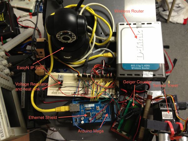
An IP cam from EasyN was ordered and installed to monitor the surroundings and inspect possible radiation sources.
Hardware Setup
The router used in this setup required 5-9 volts to power. So It was simply connected to the 8.5 volt rail directly from the NIMH battery.
The suggested IP cam requires 5 volts. An attempt was made to power the IP cam from the 5 volt power supply on the Arduino however there were some significant overheating issues on the Arduino's voltage regulator. Therefore it was decided to add a dedicated voltage regulator to the breadboard for the IP cam. A head sink was machined from a small block of aluminum to help dissipate excess heat. This setup has proven to be consistent and reliable for long periods of operation. The IP cam was then connected to the router via ethernet cable and assigned a static IP address.
At this point the system was powered on and tested. At this point checking the voltage regulator for overheating is highly recommended.
The Arduino ethernet shield on the Arduino Mega, connected to the router via ethernet cable. The Mega was powered directly from the 8.5 volt NIMH battery.
The geiger counter kit was powered from the Arduino Mega's 5v power supply. A wire connects the geiger counter's tx pin to the Mega's rx1 pin. Now a universal television remote was programed to the Sony code and used to change the serial communication period to 2-5 seconds. Also geiger bot mode was activated. This way the geiger counter only sends the counts per minute data (CPM) over serial and the data is easier and faster to parse. Further instructions on using the TV remote can be found [https://sites.google.com/site/diygeigercounter/software-features here]
Software Modifications
Arduino:
The Arduino mega was programed to receive and parse the serial data from the geiger counter. This was done by appending bytes to a string as they were received then converting them to integers. The geiger counter was found to take noisy measurements when taken over a short period of time. Since it was desirable to update geiger readings frequently an integrator was implemented to average over the last 30 geiger counter measurements. Download the class here geiger.zip for further details.
In the allModesActions described in GUI for tele-operating an E-Maxx for Remote Surveillance using Arduino and Cocoa Development the ethernet controller class controller.zip was used to send a packet to the GUI. The code snipped below was inserted into allModesActions();
if(myGeiger.update()){ update refreshes the serial buffer and the CPM value, it returns true if there is a new message myCon.sendCmd(“cpm:”, myGeiger.averageCPM() ); send a command of the form cpm:123
    Serial.print("geiger ");   // debug
    Serial.println(myGeiger.averageCPM());  // debug
  }
Cocoa:
A new NSLevelIndicator NSLabel was added to the GUI created it GUI for tele-operating an E-Maxx for Remote Surveillance using Arduino and Cocoa Development. See Image. New outlets were created syntesized in AppDelegate.h and AppDelegate.M respectively
AppDelegate.h
@property (weak) IBOutlet NSLevelIndicator *cpmBar;
@property (weak) IBOutlet NSTextField *cpmVal;
AppDelegate.m
@synthesize cpmBar;
@synthesize cpmVal;
the following method must be modified in order to listen for the new command from the Arduino Mega.
(BOOL)onUdpSocket:(AsyncUdpSocket *)sock
   didReceiveData:(NSData *)data
          withTag:(long)tag
         fromHost:(NSString *)host
             port:(UInt16)port
The command is of the form cpm:123. So the following code was inserted much like was done in the last tutorial.
 if ([msg rangeOfString:@"cpm:"].location != NSNotFound){
      NSRange range = [msg rangeOfString:@"cpm:"];
      NSString *substring = [[msg substringFromIndex:NSMaxRange(range)] stringByTrimmingCharactersInSet:[NSCharacterSet whitespaceCharacterSet]];
      NSLog(@"%@",substring);
      [cpmVal setStringValue:substring];

      [cpmBar setFloatValue:[substring floatValue]];
  }
Testing and results
See video for a full demonstration of the new features. youtube link
The IP cam was found to have a low frame rate and is difficult to control when the wifi signal is anything less than optimal. There was also a significant delay in the video so the operator would often over compensate on controls.
Even with the heat sink on the voltage regulator for the IP cam would get quite hot. A new method of stepping down the voltage is desired. Perhaps a simple voltage divider will be attempted.
The on screen controls for manual operation were effective. However, it is believed that a keyboard or joystick input would allow for easier operation.
A graph is desired for the sonic ranger data and radiation data. A polar plot could be used for the ranges to get a RADAR like image. A graph of CPM over time is desired for radiation levels.


