This is an old revision of the document!
Table of Contents
Vanishing point detection for corridors and hallways
Introduction
Last tutorial we implemented probabilistic hough transform through the bottom camera of the ardrone and implemented line follow using simple proportional controller. This tutorial I will be discussing something little advanced which has been used in autonomous navigation of ground vehicles and aerial vehicles in environments like corridor and hallways.
Vanishing point
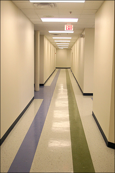
When walking through a hallway or corridor once can easily see four lines drawn to the ends of the hall. These are lines formed by the intersection of the floor and the wall.The intersection of these lines will be our vanishing point.Following the point will set the drone in the middle of the path without bumping into the walls.
Mathematics behind the detection of vanishing point
One has go through the basic steps when detecting the vanishing point.
Step 1: Detect lines in the frame
Step 2: Find the slope of the lines
Step 3: Using the slope filter out horizontal and vertical lines.
Step 4: Filtering unnecessary lines we would be having the diagonal lines
Step 5: Calculate the intersection of the diagonal lines.
Step 6: The point with the highest number of intersections would be the vanishing point.
Understanding the output
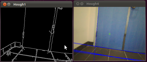
Before we go to the program there are certain things that you need to know in order to comprehend the output. The lines drawn are in two colors which is blue and red. The blue lines are the lines which are present in the image before filtering and the red lines would be the exact diagonal lines.
Upload the code
step 1: Go to folder named “src” in the ROS package “roscv”(which you would have created in the previous tutorials and create a file called “vandet.cpp”
step 2: In the empty file and paste the following code and after that save the file.
- vandet.cpp
#include <ros/ros.h>
#include <stdio.h>
#include <iostream>
#include "std_msgs/String.h"
#include <image_transport/image_transport.h>
#include <cv_bridge/cv_bridge.h>
#include <sensor_msgs/image_encodings.h>
#include <opencv2/imgproc/imgproc.hpp>     //make sure to include the relevant headerfiles
#include <opencv2/highgui/highgui.hpp>
#include <opencv/cv.h>
#include <opencv/highgui.h>
#include <cv_bridge/CvBridge.h>
#include <cvaux.h>
#include<math.h>
#include <cxcore.h>
#include "turtlesim/Velocity.h"

/*here is a simple program which demonstrates the use of ros and opencv to do image manipulations on video streams given out as image topics from the monocular vision
of robots,here the device used is a ardrone(quad-rotor).*/
using namespace std;
using namespace cv;
namespace enc = sensor_msgs::image_encodings;

static const char WINDOW[] = "Image window";

class ImageConverter
{
  ros::NodeHandle nh_;
  ros::NodeHandle n;
 ros::Publisher pub ;
  ros::Publisher tog;

  image_transport::ImageTransport it_;
  image_transport::Subscriber image_sub_; //image subscriber
  image_transport::Publisher image_pub_; //image publisher(we subscribe to ardrone image_raw)
  std_msgs::String msg;
public:
  ImageConverter()
    : it_(nh_)
  {


      pub= n.advertise<turtlesim::Velocity>("/drocanny/vanishing_points", 500);//
      image_sub_ = it_.subscribe("/ardrone/image_raw", 1, &ImageConverter::imageCb, this);
      image_pub_= it_.advertise("/arcv/Image",1);

      cvNamedWindow("Hough",CV_WINDOW_NORMAL);
  }

  ~ImageConverter()
  {
    cv::destroyWindow(WINDOW);
  }

  void imageCb(const sensor_msgs::ImageConstPtr& msg)
  {

     sensor_msgs::CvBridge bridge;//we need this object bridge for facilitating conversion from ros-img to opencv
   IplImage* img = bridge.imgMsgToCv(msg,"rgb8");  //image being converted from ros to opencv using cvbridge

   turtlesim::Velocity velMsg;


       CvMemStorage* storage = cvCreateMemStorage(0);
        int vcount=-1;
        CvSeq* lines = 0;
       int i,j,d;
	float c;
       float c1[50];
       float m;
       float dis;
       int k=0,k1=0;
      float xvc[500];
      float yvc[500];
      int xyh[700];
      int count=0;
     float m1[50];
      float xv;
      float yv;
      int vc=0;
     float xvan=0,yvan=0;
      static float xvan1=0,yvan1=0;
    float num=0;
   static float count1=0;
  float dv;
  float vanish[320][240][1];
float vxx,vyy;
float big[1][1][3];

        IplImage* out1 = cvCreateImage( cvGetSize(img), IPL_DEPTH_8U, 3 );   //make sure to feed the image(img) data to the parameters necessary for canny edge output
        IplImage* gray_out = cvCreateImage( cvGetSize(img), IPL_DEPTH_8U, 1 );
        IplImage* canny_out = cvCreateImage( cvGetSize(img), IPL_DEPTH_8U, 1 );
        IplImage* gray_out1=cvCreateImage( cvGetSize(img), IPL_DEPTH_8U, 3 );

        cvSmooth( img, out1, CV_GAUSSIAN, 11, 11 );
         cvCvtColor(img , gray_out, CV_RGB2GRAY);
        cvCanny( gray_out, canny_out,0, 190, 3 );
      cvCvtColor(canny_out ,gray_out1, CV_GRAY2BGR);


     lines = cvHoughLines2( canny_out, storage, CV_HOUGH_STANDARD, 1, CV_PI/180, 110, 0, 0 );

   for( i = 0; i < MIN(lines->total,100); i++ ) //hough standard transform
        {
             d=0;
             c=0;
            float* line = (float*)cvGetSeqElem(lines,i);
            float rho = line[0];
            float theta = line[1];
            CvPoint pt1, pt2;

            double a = cos(theta), b = sin(theta);
            double x0 = a*rho, y0 = b*rho;
            pt1.x = cvRound(x0 + 1000*(-b));
            pt1.y = cvRound(y0 + 1000*(a));
            pt2.x = cvRound(x0 - 1000*(-b));
            pt2.y = cvRound(y0 - 1000*(a));
            if(pt1.x-pt2.x==0)
             {
           pt1.x=0;
           pt1.y=0;
	   pt2.x=0;
	   pt2.y=0;
              c=1;
             }

if(pt1.x-pt2.x==0)
{
          pt1.x=0;
           pt1.y=0;
	   pt2.x=0;
	   pt2.y=0;
           d=1;
}
m=-cos(theta)/sin(theta);
c=rho*(1/sin(theta));
printf("%f\n",m);
cvLine(img, pt1, pt2, CV_RGB(0,0,255), 1, 8 );

if(abs(m)>0.5 && abs(m)<5)
{
cvLine(img, pt1, pt2, CV_RGB(255,0,0), 1, 8 );
m1[count]=m;
c1[count]=c;
count=count+1;
}

}
count=count-1;
for(i=0;i<=500;i++)
 xyh[i]=0;

for(k=0;k<=count;k++)
{
for(k1=k+1;k1<=count;k1++)


{

if(abs(m1[k])-abs(m1[k1])>=0.1)
{

xv=abs((c1[k1]-c1[k])/(m1[k]-m1[k1]));
yv=abs((m1[k1]*xv)+c1[k1]);

if(yv>0 && yv<240 && xv>0 && xv<320 )
{

vcount=vcount+1;

cvCircle(img,cvPoint(xv,yv),5,cvScalar(255,0,0),1);
xvc[vcount]=xv;
yvc[vcount]=yv;
xyh[vcount]=xyh[vcount]+1;

}

}


}
}


}

}


count=0;
vcount=-1;


if((c==0)&&(d==0))
m=abs((line[1].y-line[0].y)/(line[1].x-line[0].x));

if(m<4 && m>0)
cvLine( img, line[0], line[1], CV_RGB(0,255,0), 2, 8 );


}

m1[count]=(line[1].y-line[0].y)/(line[1].x-line[0].x);
c1[count]=(line[0].y)-(m1[count]*line[0].x);
count=count+1;

if(count)
{
xvan=0;
yvan=0;
num=0;

for(k=0;k<=count;k++)

{
for(k1=k+1;k1<=count;k1++)

{

if(m1[k]-m1[k1]!=0)
{

xv=abs((c1[k1]-c1[k])/(m1[k]-m1[k1]));
yv=abs((m1[k1]*xv)+c1[k1]);

}


if(yv>30&&yv<=245&&xv>30&&xv<320)
{
xvan=xv+xvan;
yvan=yv+yvan;
num=num+1;

vxx=xvan/num;
vyy=yvan/num;


cvCircle(out1,cvPoint(xv,yv),5,cvScalar(255,0,0),1);

}
}
}
}


}
}

}
}

xvan1=xvan1+(xvan/num);
yvan1=yvan1+(yvan/num);
count1=count1+1;


       cvCircle(img,cvPoint(160,120), 3, cvScalar(0,255,100),1);


      cv::waitKey(2);
   cvShowImage( "Hough1", gray_out1 );
         cvShowImage( "Hough4", img);


}

};

int main(int argc, char** argv)
{
  ros::init(argc, argv, "image_converter");
  ImageConverter ic;
  ros::spin();
  return 0;
}
Make changes in the CMakelinefollowerLists.txt
Step 1: Open up the file named “CMakeLists.txt” and search for the lines beginning with “rosbuild_add_executable”. In that add the file you created which is “vandet.cpp”. Save and close the file.
Test the code
Set the quad-rotor in a hallway or a corridor like in the pictures described above.
Step 1: Connect to the ardrone Step 2: Open up a terminal and enter the commands one after the other:
roscd roscv
cmake .
rosmake
Step 3: Enter the following commands in separate terminal
roscore
rosrun ardrone_brown ardrone_driver
rosrun roscv roscv
Here are some pictures of the vanishing point detection when the code was tested.
As per the algorithm in my code when you face the vertical or horizontal lines it would be in blue color. Here are some pictures of that.


