Table of Contents
LIDAR on E-Maxx for SLAM
Arduino Attempt
Since most of the project was already Arduino based the feasibility of reading LIDAR data directly to an Arduino was examined. The setup involved the Sain-Smart USB host shield that was used for the Measuring odometry with an optical mouse tutorial. The LIDAR used was the Hokuyo URG-04LX. The lidar was powered through it's serial connector port. The Arduino mega was connected to the LIDAR via usb cable.
The Arduino mega was uploaded with the ACM_terminal example sketch provided with the usb host shield library. This sketch will simply echo commands from a computer to the device connected to the usb host shield. The following command was sent to the lidar to configure it to scip2.0 mode
scip2.0\n
the Hokuyo echoed
scip2.0
0
indicating that the mode change was successful. However, this command took over 30 seconds to receive. An “MD” command was sent to the LIDAR to recieve a set of scans. Still, there was an excessively long delay in response.
To establish a benchmark for response delay the LIDAR was connected to a laptop. The SCIP 2.0 responses were almost immediate. It was suspected that the example Arduino sketch was causing slow downs so a simple sketch was created to send a simple request for the LIDAR's software version information. Still, the problem persisted.
Earlier in this project Arduino slowdowns were encountered when the power draw was too high on the Arduino board. So Ample power was supplied to the Arduino board using a power supply. The LIDAR was powered separately at 5.0 V. Still, there was no effect on the speed.
At this point it was decided to pursue other means of processing LIDAR data. Even if the speed problem was solvable here it is unlikely that and Arduino mega could efficiently run a SLAM algorithm
Slam On Linux and ROS
It was decided to utilize ROS (robot operating system) to process the LIDAR data. Additionally ROS has several SLAM packages available for use. I believed small linux board should be able to run ROS, the LIDAR drivers and a slam package. A Raspberry Pi was selected for this purpose.
Hector slam was selected as a slam package due to it's scalability. Hector slam can be used with odometry, IMU data, and LIDAR data or just LIDAR data. This way it would be possible to create a basic setup using only LIDAR. From that basic it would be possible setup odometry and IMU data as time allowed.
Both Hector SLAM and thee LIDAR drivers were last updated before the release of ROS groovy. Therefore, it was decided to use ROS fuerte for full compatibility.
While waiting for the Raspberry Pi to arrive a laptop was used to run ROS on Ubuntu.
Installing and Testing LIDAR Drivers
The laser_drivers package was selected to run the LIDAR for it's direct compatibility with the Hokuyo LIDAR. The laser driver was installed by follwing this tutorial. Installation and testing was pretty straightforward when following the tutorial.
The hokuyo node, once running, will broadcast a topic called “scan” streaming the laser data with each sweep. The scan data will be shown in the “laser” reference frame.
Installing Hector Slam
First the hector slam source needs to be installed. You can download them directly and move them to your ros workspace or you clone them directly
roscd
cd sandbox ## the name of my folder to hold libraries
Now it is necessary to build the package
rosbuild hector_slam
If the build fails you may want to use
rosdep install hector_slam
to add the necessary dependencies to run rosmake again
after hector slam is installed test it by following the mapping using logged data tutorial on the ROS wiki
Configuring hector SLAM to use LIDAR data
The following procedure it based on this ROS answers page.
First it is necessary to create a ROS package by navigating to your ROS workspace and entering
navigate to location:
$ roscd
$ cd sandbox
create package:
$ roscreate-pkg slam_launch
$ rospack profile
$ rospack find slam_launch
in the newly created slam launch package create the following files in ~/fuerte_workspace/sandbox/slam_launch/launch/
slam.launch
<launch>

<param name="/use_sim_time" value="false"/>ros

<node pkg="rviz" type="rviz" name="rviz"
args="-d $(find hector_slam_launch)/rviz_cfg/mapping_demo.vcg"/>

<include file="$(find slam_launch)/launch/hector_mapping.launch"/>

<include file="$(find slam_launch)/launch/geotiff_mapper.launch">
<arg name="trajectory_source_frame_name" value="scanmatcher_frame"/>
</include>

</launch>
hector_mapping.launch
<launch>

<node pkg="hector_mapping" type="hector_mapping" name="hector_mapping"    output="screen">

<param name="pub_map_odom_transform" value="true"/>
<param name="map_frame" value="map" />
<param name="base_frame" value="base_link" />
<param name="odom_frame" value="base_link" />
<!-- Map size / start point -->
<param name="map_resolution" value="0.025"/>
<param name="map_size" value="2048"/>
<param name="map_start_x" value="0.5"/>
<param name="map_start_y" value="0.5" />
<param name="laser_z_min_value" value="-2.5" />
<param name="laser_z_max_value" value="7.5" />

<!-- Map update parameters -->
<param name="update_factor_free" value="0.4"/>
<param name="update_factor_occupied" value="0.7" />
<param name="map_update_distance_thresh" value="0.2"/>
<param name="map_update_angle_thresh" value="0.06" />
</node>

<node pkg="tf" type="static_transform_publisher" name="base_to_laser_broadcaster"      args="0 0 0 0 0 0 /base_link /laser 100" />

</launch>
notice the following line in the above code
<node pkg="tf" type="static_transform_publisher" name="base_to_laser_broadcaster" args="0 0 0 0 0 0 /base_link /laser 100" />
it is used to create the static transform broadcaster to the base_link frame. More details on the setup of the hector_slam reference frames can be found here.
geotiff_mapper.launch
in this file simply chance the location of your save file marked by in the code below.
<launch>
<arg name="trajectory_source_frame_name" default="/base_link"/>
<arg name="trajectory_update_rate" default="4"/>
<arg name="trajectory_publish_rate" default="0.25"/>

<node pkg="hector_trajectory_server" type="hector_trajectory_server" name="hector_trajectory_server" output="screen">
<param name="target_frame_name" type="string" value="/map" />
<param name="source_frame_name" type="string" value="$(arg trajectory_source_frame_name)" />
<param name="trajectory_update_rate" type="double" value="$(arg trajectory_update_rate)" />
<param name="trajectory_publish_rate" type="double" value="$(arg trajectory_publish_rate)" />
</node>


<node pkg="hector_geotiff" type="geotiff_node" name="hector_geotiff_node" output="screen" launch-prefix="nice -n 15">
<remap from="map" to="/dynamic_map" />
<param name="map_file_path" type="string" value="<!--  YOUR SAVE PATH HERE -->" />
<param name="map_file_base_name" type="string" value="uprobotics" />
<param name="geotiff_save_period" type="double" value="0" />
<param name="draw_background_checkerboard" type="bool" value="true" />
<param name="draw_free_space_grid" type="bool" value="true" />
</node>

</launch>
starting the slam_launch package:
in terminal window 1 launch the roscore
$ roscore
in terminal window 2 setup the LIDAR permissions and start the node
$ sudo chmod a+rw /dev/ttyACM0
$ s -l /dev/ttyACM0
$ rosrun hokuyo_node hokuyo_node
In terminal window 3 launch your package
$ roslaunch slam_launch slam.launch
Now a RViz window will open and display SLAM data
LIDAR Vehicle setup
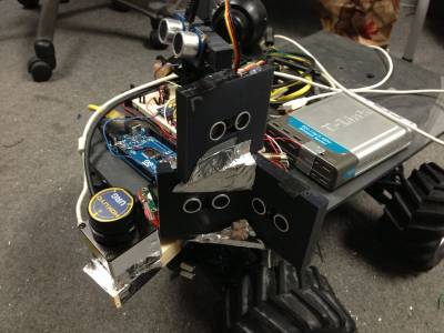
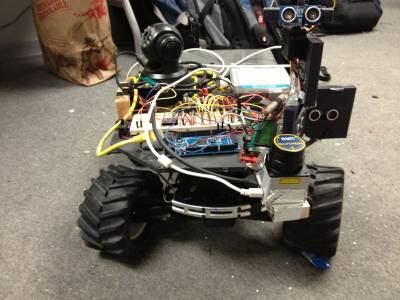
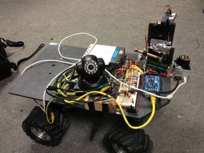
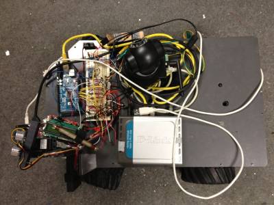
The lidar was placed on the front of the vehicle in front of the sonic rangefinders. The location of the LIDAR was in a “blindspot” of the sonic sensors so as to not interfere with them so they could continue to operate the vehicle in autonomous mode. The LIDAR was placed far enough foreword so that none of the structure on the vehicle would block its sweeping area (~270 degrees).
Results from tethered SLAM test
the results of running the slam package without odometry or IMU data using a laptop running ubuntu can be seen in the following video. The laptop was tethered to the vehicle using a USB cable.
Unfortunately since the vehicle was tethered it was not possible to test it in the ductwork assembly so a hallway was used.
Though the map generated was representative of the test area the the effect of no odometry data can still be seen in curved sides on the map.
ROS and SLAM on the Raspberry Pi
The following tutorial was used to install ROS on the raspberry pi Raspberry Pi. NOTE: this installation process will take about 2 hours due to build times.
ROS packages were found to be difficult to install on the raspberry pi due to isues with dependencies. After trying several different methods of installing the only way found to intall them was to individually include all of the packages. For example, to install laser_drivers.
rosdep was used to install find the missing package dependencies.
$ rosdep install laser_drivers
This would list the dependencies but it would not install them. The individual packages were downloaded and installed using rosmake. Even still the package was not able to be successfully installed as I was unable to locate a ROS fuerte version of driver_common library
No further solutions were found to installing the slam package on the raspberry pi to date due to raspberry pi arriving a week later than expected.


